CRT
0...30min Compressor rest time. The output is switched on again after CRT minutes have elapsed since the
previous switchover. We recommend to set CRT=03 with HYS<2.0°.
CT1
0...30min Thermostat output run when probe T1 is faulty. With CT1=0 the output will always remain OFF.
CT2
0...30min Thermostat output stop when probe T1 is faulty. With CT2=0 and CT1>0 the output will always be ON.
Example: CT1=4, CT2= 6: In case of probe T1 failure, the compressor will cycle 4 minutes ON and 6 minutes OFF.
CSD
0..30min Compressor stop delay after the door has been opened (active only if DS=YES).
DFM
NON;
TIM;
RTC
Defrost start mode
NON : defrost function is disabled (the following parameter will be FID).
TIM : regular time defrost.
RTC : the defrost time is scheduled by parameters DH1, DH2...DH6.
DFT
0...99 hours Time interval among defrosts. When this time has elapsed since the last defrost, a new defrost cycle is started.
DH1
...
DH6
HH.M Scheduled time for defrost 1 to 6. HH hours from midnight, M tens of minutes. Accepted values go from
00.0 to 23.5. After “23.5” the value is “---” that means “skipped defrost”. Example: DH1=8.3 means 8.30
AM.
DLI
-50...120° Defrost end temperature.
DTO
1...120min Maximum defrost duration.
DTY
OFF;
ELE;
GAS
Defrost type
OFF: off cycle defrost (Compressor and Heater OFF).
ELE: electric defrost (Compressor OFF and Heater ON).
GAS: hot gas defrost (Compressor and Heater ON).
DPD
0...240sec Evaporator pump down. At the beginning of defrost, defrost outputs (determined by DTY) are OFF for
DPD seconds.
DRN
0...30min Pause after defrost (evaporator drain down time).
DDM
R T;
LT;
SP;
DEF
Defrost display mode. During defrost the display will show:
RT: the real temperature;
LT : the last temperature before defrost;
SP : the current setpoint value;
DEF : “dEF”.
DDY
0...60min Display delay. The display shows the information selected with parameter DDM during defrost and for
DDY minutes after defrost termination.
FID
NO/YES Fans active during defrost.
FDD
-50...120° Evaporator fan re-start temperature after defrost.
FTO
0...120min Maximum evaporator fan stop after defrost.
FCM
NON;
TMP;
TIM
Fan mode during thermostatic control.
NON : The fans remain ON all the time;
TMP : Temperature-based control. The fans are ON when the compressor is ON. When the compressor
is turned OFF, the fans remain ON as long as the temperature difference Te-Ta is greater than FDT. The
fans are turned ON again with FDH differential. (Te = Evaporator temperature, Ta = Air temperature);
TIM : Timed-based control. The fans are
ON when the compressor is ON. When the
compressor is OFF, the fans switch ON and
OFF according to parameteres FT1, FT2,
FT3 (See Fig.2).
FDT
-120...0° Evaporator-Air temperature difference for the fans to turn OFF after the compressor has stopped.
FDH
1...120° Temperature differential for fan re-start.
Example: FDT = -1, FDH=3. In this case, after the compressor has stopped, the fans are OFF when Te
> Ta - 1 (FDT), whereas the fans are ON when Te < Ta - 4 (FDT-FDH).
FT1
0...180sec Fan stop delay after compressor stop. See Fig. 2
FT2
0...30min Timed fan stop. With FT2=0 the fans remain on all the time.
FT3
0...30min Timed fan run. With FT3=0, and FT2 > 0, the fans remain off all the time.
ATM
NON;
ABS;
REL
Alarm threshold management.
NON : all temperature alarms are inhibited (the following parameter will be ADO).
ABS : the values programmed in ALA and AHA represent the real alarm thresholds.
REL : the values programmed in ALR and AHR are alarm differentials referred to SP and SP+HYS.
Fig.2 Time-optimised fan control (FCM=TIM)
Temperature alarm with relative thresholds,
refrigerating control (ATM=REL, C-H=REF).
Temperature alarm with relative thresholds,
heating control (ATM=REL, C-H=HEA).
TECHNICAL DATA
Power supply
AR2-5.…D 12Vac/dc ±10%, 3W
AR2-5....W 110 - 230Vac±10%, 50/60Hz, 3W
Relay output
Compressor 12(5)A 240Vac
Defrost 7(2)A 240Vac
Evap. Fan 8(3)A 240Vac
Auxiliary loads 7(2)A 240Vac
Input
NTC 10KΩ@25°C LAE Part No. SN4...
PTC 1000Ω@25°C LAE Part No. ST1…
Measurement Range
-50…120°C, -55…240°F
-50 / -9.9 … 19.9 / 80°C (NTC10K only)
Measurement accuracy
<0.5°C within the measurement range
Real Time Clock battery
>150 hours; self-rechargeable
Operating conditions
-10 … +50°C; 15%...80% r.H.
CE (Reference norms)
EN60730-1; EN60730-2-9;
EN55022 (Class B);
EN50082-1
VIA PADOVA, 25
31046 ODERZO /TV /ITALY
TEL. +39 - 0422 815320
FAX +39 - 0422 814073
www.lae-electronic.com
E-mail: sales@lae-electronic.com
ADO
0... 30min
Delay before door open alarm warning.
AHM
NON;
ALR;
STP;
Operation in case of high condenser alarm
NON : high condenser alarm inhibited.
ALR : in case of alarm, “HC” ashes in the display and the buzzer is switched on.
STP : in addition to the alarm symbols displayed, the compressor is stopped and defrosts are suspended.
AHT
-50...120°
Condensation temperature alarm (referred to T3 probe).
ACC
0...52
weeks
Condenser periodic cleaning. When the compressor operation time, expressed in weeks, matches the
ACC value programmed, “CL” ashes in the display. With ACC=0 the condenser cleaning warning is
disabled and CND disappears from Info Menu.
IISM
NON;
MAN;
HDD;
DI2
Switchover mode to second parameter set
NON : inhibition to use the second parameter group (the following parameter will be SB).
MAN : button switches the two parameter groups over.
HDD : automatic switchover to the second parameter group, when heavy duty conditions are detected.
DI2 : switchover to the second parameter group when the auxiliary DI2 input makes.
IISL
-50... IISH
Minimum limit for IISP setting.
IISH
IISL... 120°
Maximum limit for IISP setting.
IISP
IISL... IISH Setpoint in mode 2.
IIHY
1... 10° OFF/ON differential in mode 2.
IIFC
NON;TMP;
TIM
Fan control in mode 2. See FCM.
HDS
1...5 Controller sensitivity for the automatic switchover from Group I to Group II (1=minimum, 5=maximum).
IIDF
0...99 hours Time interval among defrosts in mode 2.
SB
NO/YES
Stand-by button enabling.
DS
NO/YES Door switch input enabling (closed when door is closed).
DI2
NON;
HPS;
IISM;
RDS;
DSY
DI2 digital input operation
NON : digital input 2 not active.
HPS : when contact opens a condensing unit high pressure alarm occurs.
IISM : when contact makes the controller will use group 2 parameters.
RDS : when contact makes a defrost is started (remote control).
DSY : defrost synchronisation. The controllers, linked as per Fig. 3, will all start and end defrost together.
The rst controller in defrost will get defrost of all the others started. The last controller ending defrost will
get defrost of all the others stopped.
LSM
NON;
MAN;
DOR
Light control mode
NON : light output not controlled.
MAN : light ouput controlled through button (if OA1=LGT).
DOR : light ouput switched on when door is opened (if OA1=LGT).
OA1
NON;
0-1;
LGT;
2CU;
2EU;
AL0;
AL1
AUX output operation
NON : output disabled (always off).
0-1 : the relay contacts follow the on/standby state of controller.
LGT : output enabled for light control.
2CU : output programmed for the control of an auxiliary compressor.
2EU : output enabled for the control of the electrical defrost of a second evaporator.
AL0 : contacts open when an alarm condition occurs.
AL1 : contacts make when an alarm condition occurs.
2CD
0...120 sec Auxiliary compressor start delay. If OA1=2CU the auxiliary output is switched on with a delay of 2CD
seconds after the main compressor has cut-in. Both compressors are turned off at the same time.
INP
SN4; ST1 Temperature sensor selection. With INP=SN4, the probes must be the LAE models SN4..; with INP =
ST1, the probes must be the LAE models ST1...
OS1
-12.5..12.5°C Probe T1 offset.
T2
NO/YES Probe T2 enabling (evaporator).
OS2
-12.5..12.5°C Probe T2 offset.
T3
NON;
DSP;
CND;
2EU
Auxiliary probe T3 operation
NON : probe T3 not tted.
DSP : temperature T3 to be displayed.
CND : condenser temperature measurement.
2EU : second evaporator temperature measurement.
OS3
-12.5..12.5°C Probe 3 offset.
TLD
1...30 min Delay for minimum temperature (TLO) and maximum temperature (THI) logging.
SIM
0...100 Display slowdown.
ADR
1...255 AR2-5 address for PC communication.
WIRING DIAGRAMS
DISPLAY
During normal operation, the display shows either the temperature measured or one of the following indications:
Defrost in progress Condenser high pressure alarm
Controller in stand-by Room high temperature alarm
Condenser clean warning Room low temperature alarm
Door open alarm Probe T1 failure
Condenser high temperature alarm Probe T2 failure
Probe T3 failure
INFO MENU
The information available in this menu is:
Instant probe 1 temperature Maximum probe 1 temperature recorded
*
Instant probe 2 temperature Minimum probe 1 temperature recorded
*
Instant probe 3 temperature
**
Compressor working weeks
Minutes of the Real Time Clock Keypad state lock
Hours of the Real Time Clock
*: displayed only if enabled (see §Conguration Parameters) **: displayed only if ACC > 0
Access to menu and information displayed.
Press and immediately release button ■ .
With button ■ or select the data to be displayed.
Press button ■ to display value.
To exit from the menu, press button ■ or wait for 10 seconds.
Reset of THI, TLO, CND recordings
With button ■ or select the data to be reset.
Display the value with button ■ .
While keeping button ■ pressed, use button .
STAND-BY
Button , when pressed for 3 seconds, allows the controller to be put on a standby or output control to be resumed (with SB=YES only).
KEYPAD LOCK
The keypad lock avoids undesired, potentially dangerous operations, which might be attempted when the controller is operating in
a public place. In the INFO menu, set parameter LOC=YES to inhibit all functions of the buttons. To resume normal operation of
keypad, adjust setting so that LOC=NO.
SELECTION OF SECOND PARAMETER GROUP
It’s possible to select control parameters between two different pre-programmed groups, in order for the fundamental control
parameters to be adapted quickly to changing needs. Changeover from Group I to Group II (and vice versa) may take place
MANUALLY by pressing button for 2 seconds (with IISM=MAN), or AUTOMATICALLY when heavy duty conditions are detected
(with IISM=HDD), or when IISM=DI2 and the AUXILIARY INPUT DI2 is activated (the activation of DI2 selects Group II). If
IISM=NON, switchover to Group II is inhibited. The activation of Group II is signalled by the lighting up of the relevant LED on the
controller display.
REAL TIME CLOCK SETTING
The Real Time Clock (RTC) can be adjusted directly from the Info Menu (see Setpoint modication procedure). Tens of minutes
MIN range from 0 to 59 and Hours HRS range from 0 to 23. If RTC is adjusted just before an upcoming change of hour, verify the
correctness of the setting again. The RTC does not automatically change upon Daylight Saving Time.
DEFROST
Automatic defrost. Defrost starts automatically at xed time-intervals or at programmed scheduled (up to six per 24 hours).
Timed defrost ■ . With DFM=TIM defrosts take place at regular intervals when the timer reaches the value of DFT. For example,
with DFM=TIM and DFT=06, a defrost will take place every 6 hours.
Scheduled defrost ■ . With DFM=RTC defrost takes place at time specied by DH1...DH6. The format of time is “HH.M”, where
HH are hours and M are tens of minutes. To disable one or more of the 6 scheduled defrosts, assign the value “---” (it is the value
after “23.5”). Parameters DH1...DH6 are accessible both in the setup (see §Conguration Parameters) and by keeping button
pressed for 4 seconds during normal operation.
Synchronised defrost ■ . With DI2=DSY and when more units (models AR2-5x3xxx only) are linked to each other as per Fig.
3, synchronised defrosts of all linked controllers will take place. The rst controller which will start defrost, will also get all other
controllers synchronised.
Manual or remote defrost start ■ . If DFM=TIM it’s possible to manually start a defrost, by pressing button for 4 seconds. If
DFM=RTC hold button down for 4 seconds to display DH1, then press button again for 4 seconds to manually start a defrost.
Defrost may be also started remotely, if DI2=RDS, through the making of the auxiliary contact DI2.
Defrost type. Once defrost has started, Compressor and Defrost outputs are controlled according to parameter DTY. If FID=YES,
the evaporator fans are active during defrost.
Defrost termination. The actual defrost duration is inuenced by a series of parameters.
Time termination ■ : T2=NO and T3 different from 2EU: the evaporator temperature is not monitored and defrost will last as long
as time DTO.
Temperature monitoring of one evaporator ■ : T2=YES and T3 different from 2EU. In this case, if the sensor T2 measures the
temperature DLI before the time DTO elapses, defrost will be terminated in advance.
Temperature monitoring of two evaporators ■ : T2=YES, T3=2EU, OAU=2EU. This function is for the control of two independent
evaporators and it switches off the individual heating of the evaporator which gets to temperature DLI rst, waiting for the second
evaporator to get to that temperature before the time DTO elapses.
Resuming thermostatic cycle. When defrost is over, if DRN is greater than 0, all outputs will remain off for DRN minutes, in
order for the ice to melt completely and the resulting water to drain. Moreover, if probe T2 is active (T2=YES), the fans will re-start
when the evaporator gets to a temperature lower than FDD; Vice versa, if probe T2 is not active (T2=NO) or after defrost has
come to an end, such condition does not occur by end of the time FTO, after FTO minutes have elapsed the fans will be switched
on anyway.
Caution: if DFM=NON or C-H=HEA all defrost functions are inhibited; if DFT=0, automatic defrost functions are excluded. During
a high pressure alarm, defrost is suspended. During defrost, high temperature alarm is bypassed.
OPERATION
Insert the controller through a hole measuring 71x29 mm. ■
Make sure that electrical connections comply with the paragraph “wiring diagrams”. To reduce the effects of electromagnetic ■
disturbance, keep the sensor and signal cables well separate from the power wires.
Fix the controller to the panel by means of the suitable clips, by pressingly gently; if tted, check that the rubber gasket adheres ■
to the panel perfectly, in order to prevent debris and moisture inltration to the back of the instrument.
Place the probe T1 inside the room in a point that truly represents the temperature of the stored product. ■
Place the probe T2 on the evaporator where there is the maximum formation of frost. ■
The function of probe T3 is determined by the parameter T3. With ■ T3=DSP the probe measures the temperature to be displayed.
With T3=CND the probe measures the condenser temperature, it must therefore be placed between the ns of the condensing
unit. With T3=2EU the probe measures the temperature of the second evaporator and it must therefore be placed where there is
the maximum formation of frost. With T3=NON, the third probe is disabled.
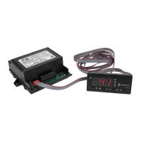
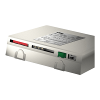
INSTALLATION
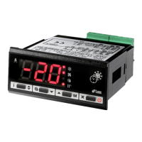
Thermostat output
Fan output
Alarm
Defrost output
Activation of 2nd parameter set
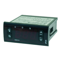
Info / Setpoint button.
Fig.1 - Front panel
Manual defrost / Decrease button.
Manual activation / Increase button.
Exit / Stand-by button.
Thank you for having chosen an LAE electronic product. Before installing the instrument, please read this instruction booklet
carefully in order to ensure safe installation and optimum performance.
DESCRIPTION
INDICATIONS
AR2-5 INSTRUCTIONS FOR USE
SETPOINT : display and modication
Press button ■ for at least half second, to display the
setpoint value.
By keeping button ■ pressed, use button or to set
the desired value (adjustment is within the minimum SPL and
the maximum SPH limit).
When button ■ is released, the new value is stored.