2
WIRING DIRECTIONS
Each Wattstopper BZ series power pack can supply power for 14 CI-305
sensors. When using more sensors than this, multiple power packs are
required.
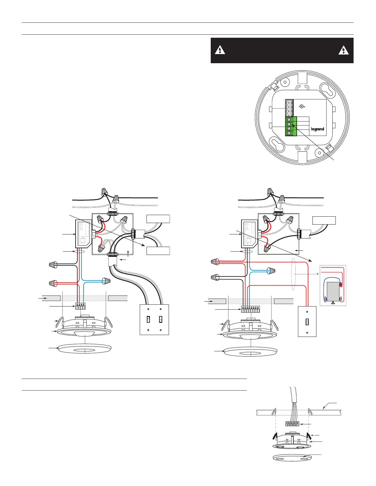
Refer to the wiring diagram for the following procedures:
Connect the low voltage:
• RED wire (+24VDC) from power pack to the +24V terminal on the sensor.
• BLACK wire (Return) from power pack to Common terminal on the sensor.
• BLUE wire from power pack to Control Out terminal on sensor.
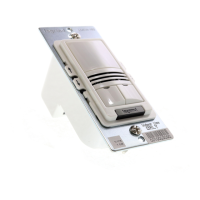
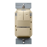
To add a manual switch such as the LVS-1 Momentary Toggle Switch, or
RS2-3 Low Voltage Momentary Switch to the above applications–connect:
• Wire from one side of switch to +24 terminal on sensor.
• Wire from other side of switch to Man Switch terminal on sensor.
Care should be taken to separate high voltage power from low voltage (Class 2)
control wiring.
All connections to sensor are low voltage, Class 2.
WARNING: TURN THE POWER OFF AT THE
CIRCUIT BREAKER BEFORE WIRING.
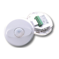
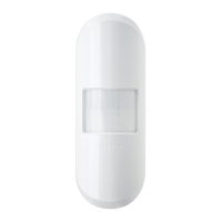
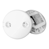
CI-305
Passive Infrared
Occupancy Sensor
Appliance
Control
88T9
E101196
+24VDC/VAC
Connect to Watt Stopper
Class 2 Power Packs
For Indoor Use Only
www.legrand.us/wattstopper
Control Out.
Man. Switch
+24V
Common
LISTED
v5
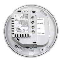
Wiring
terminals
Load #1
Load #2
(Optional)
CI-305
Standard wiring with local off switch
Rear Housing
rminal
Front Cover
Ceiling
Blue
Control Out
+24V
Common
Low Voltage
Class 2
Line
Voltage
Line
Neutral
Feed Through
Power Pack
Black
Red
#1 #2
Line Voltage
Switches
Standard wiring with local off switch
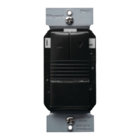
LVS-1
Load
Rear Housing
Depluggable
Te
rminal
Front Cover
Ceiling
Blue
Control Out
Black
+24V
Low Voltage
Class 2
Line Voltage
Line
Neutral
Feed Through
Power Pack
Man.Switch
Red
CI-305
Common
Man.Switch
+24V
Jumper
Back
of
LVS-1
For low voltage momentary
switch set DIP switch #7 ON
Manual-On wiring with low voltage momentary switch
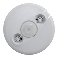
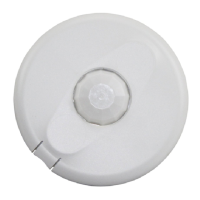
MOUNTING THE SENSOR DIRECTLY TO CEILING
1. Attach the plastic spring clips to the edge of the sensor in the slots provided.
2. Cut a 3.5” to 4” round hole in the acoustic ceiling tile at the mounting location.
A 3.5” hole is recommended for a secure fit.
3. Pull the low voltage wire from the power pack to the sensor through the hole.
4. Connect the low voltage wires to the appropriate terminals on the sensor.
5. Push the sensor up through the hole until the Spring Clips hold the sensor
securely in place.
6. Snap the front cover onto the sensor. Using an Octagonal J-Box
7. Pull the low voltage wires from the power pack into the J-Box through the conduit
knockout.
5HDU
KRXVLQJ
)URQW
&HLOLQJ
6SULQJFOLSV
Ceiling Mount
 Loading...