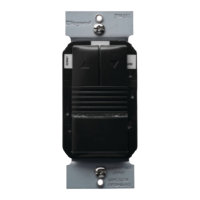
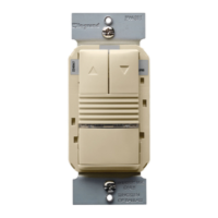
2
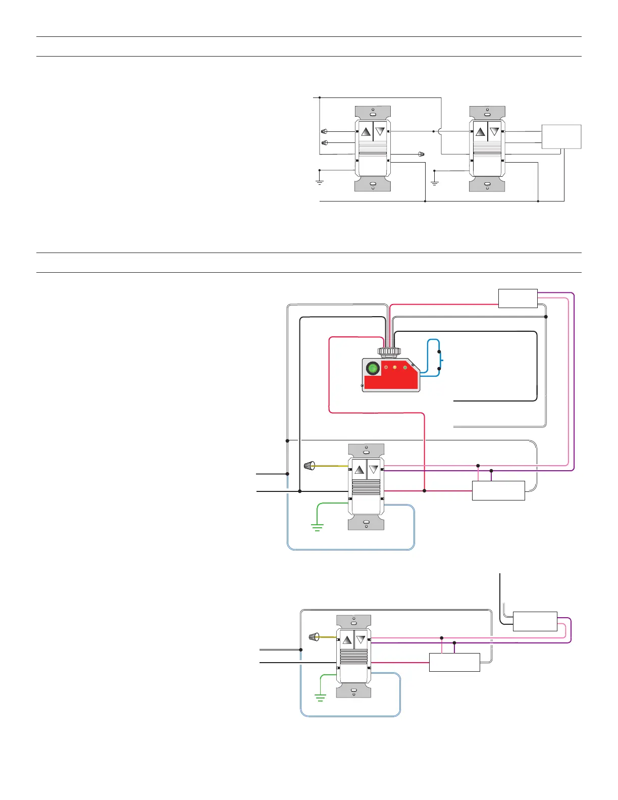
MULTI-WAY
The Multi-Way capability is available on all models. Sensors can
easily be wired together for convenient control of a common load.
When wiring this way, only use 311 series sensors. Multi-Way in
311 series is not compatible with prior sensor models.
The following principles apply for Multi-Way:
• All units should be on the same phase.
• All units can sense each other’s push button events and
respond accordingly.
• All units can sense each other’s PIR trigger event. The
response will be determined by the Light Level setting and/or
conditions of the space of the detecting sensor.
• The time delay for all units is defined by the unit with the
smallest time delay.
• All Units can sense each other’s dimming events and respond
accordingly.
NOTE: For multi-way applications, models with v3 and v2 can be combined, but cannot be used with v1 models.
Black
Purple
Black
Signal
(Blue w/
White
Stripe)
Line
Signal
(Blue w/
White
Stripe)
Ground
Green
Ground
Green
Yellow
traveler
Yellow
Red
Pink
Red
Purple
Pink
leads to dimming
ballast from one
PW-311 only
Driver
or Ballast
Typical Multi-way Wiring
(Up to 4 sensors)
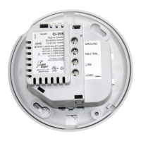
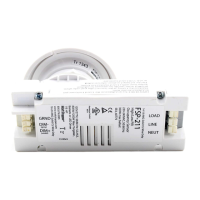
USING THE PW-311 WITH EMERGENCY LIGHTING
When used with an ELCU
Wattstopper recommends using an ELCU
device. In this scenario, the PW-311’s 0-10VDC
dimming circuit is connected to and alters the light
level of both normally powered lighting loads and
emergency powered lighting loads. The 0-10V
signal is generated by the PW-311.
When Normal Power is available:
When Normal Power is available and the normal
load has been turned off by the sensor, the ELCU
will turn off the Emergency Load as well.
When Normal Power is unavailable:
When normal power to the room controller fails
for any reason, the 0-10VDC dimming circuit in
the PW-311 will revert to an open circuit. Since no
device is controlling the 0-10V circuit, any fixture
that is fed by emergency power will go full on.
Fixtures fed by normal power will of course be off
since there is no power available for their operation.
When no ELCU is used:
In this scenario, emergency lighting cannot be turned
on or off by the sensor, only dimmed. The normal
lighting load has full control. As in the example with
the ELCU, if normal power fails, the emergency
load will go full on. If any Emergency Circuits are
fed or controlled from a panel, they must be located
electrically where fed from a UPS, generator, or other
guaranteed source of power during emergency and
power outage situations.
09860r1
Cir.#_______
Emergency
Power
Remote
Activation
Normal
Power
Push to Test
R8.5
mm
Circle
CUT-OUT
EMERGENCY CIRCUIT
Cut Jumper Loop
to use with
normally closed
- Test switch
- Fire alarm panel
- Security panel
- Other
Emergency Power In (Black)
Emergency Neutral (Gray)
Emergency Power Out (Red)
Normal Neutral (White)
Normal Switch Sense (Red)
Normal
Power
Sense
(Black)
Emergency Line
“Always On”
Emergency Neutral (White)
Unswitched
Line (Black)
Neutral
(White)
Red
Pink
Purple
Ground
Yellow
Neutral
Signal
(Blue with White Stripe)
Emergency
Lighting
Normal
Lighting
Pink
Purple
Unswitched
Line (Black)
Neutral
(White)
Red
Neutral
Normal
Lighting
Emergency Neutral
(White)
Emergency Line
“Always On”
(Black)
Emergency
Lighting
Yellow
Ground
Signal
(Blue with White Stripe)
Pink
Purple
 Loading...