Page 5
B - Compressor
10ACC-042, -048 and -060 units are equipped with a
scroll compressor. For compressor specifications see
“ELECTRICALDATA”sectioninthismanualor the com-
pressor nameplate.
SCROLL COMPRESSOR
DISCHARGE
SUCTION
FIGURE 4
1 - Scroll Compressor
The scroll compressor design is simple, efficient and re-
quires few moving parts. A cutaway diagram of the scroll
compressor is shown in figure 4.The scrolls are located in
the top of the compressor can and the motor is located just
below. The oil level is immediately below the motor.
The scroll is a simple compression concept centered
around the unique spiralshape of the scrolland its inherent
properties. Figure 5 shows the basic scroll form. Two iden-
tical scrolls are mated together forming concentric spiral
shapes (figure 6 ). One scroll remains stationary, while the
other is allowed to “orbit” (figure 7). Note that the orbiting
scroll does not rotate or turn but merely “orbits” the station-
ary scroll.
SCROLL FORM
FIGURE 5
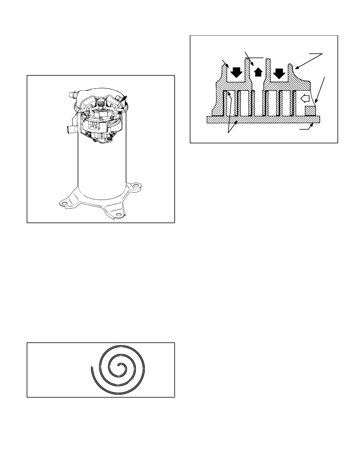
FIGURE 6
STATIONARY SCROLL
ORBITING SCROLL
DISCHARGE
SUCTION
CROSS-SECTION OF SCROLLS
TIPS SEALED BY
DISCHARGE PRESSURE
DISCHARGE
PRESSURE
The counterclockwise orbiting scroll draws gas into the out-
er crescent shaped gas pocket created by the two scrolls
(figure 7 - 1). The centrifugal action of the orbiting scroll
sealsoff theflanksofthe scrolls(figure7 -2). As theorbiting
motion continues, the gas is forced toward the center of the
scroll and the gas pocket becomes compressed (figure 7 -
3). When the compressed gas reaches the center, it is dis-
charged vertically into a chamber and discharge port in the
top of the compressor (figure 6). The discharge pressure
forcing down on the top scroll helps seal off the upper and
lower edges (tips) of the scrolls (figure 6 ). During a single
orbit,severalpockets of gasare compressedsimultaneous-
ly providing smooth continuous compression.
The scroll compressor is tolerant to the effects of liquid re-
turn. If liquid entersthe scrolls, the orbitingscrollisallowed
to separate from the stationary scroll. The liquid is worked
toward the center of the scroll and is discharged. If the
compressor is replaced, conventional Lennox cleanup
practices must be used.
Due to its efficiency, the scroll compressor is capable of
drawing a much deeper vacuum than reciprocating com-
pressors. Deep vacuum operation can cause internal fu-
site arcing resulting in damaged internal parts and will re-
sult in compressor failure. Never use a scroll compressor
for evacuating or “pumping-down”the system. This type of
damage can be detected and will result in denial of warran-
ty claims.
NOTE - During operation, the head of a scroll compressor
may be hot since it is in constant contact with discharge
gas.
 Loading...