Page 3
Electric Heat Sections
CAUTION
As with any mechanical equipment, contact with sharp
sheet metal edges can result in personal injury. Take
care while handling this equipment and wear gloves and
protective clothing.
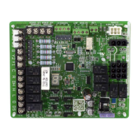
The ECB38 series electric heat sections provide eld-in-
stalled electric heat for the CBA38MV series air handler
unit. ECB38 electric heat sections are available in sin-
gle-phase and three-phase voltages. Single-phase ECB38
heat sections are equipped with either terminal blocks or
circuit breakers.
General Information
These instructions are a general guide and do not su-
persede local codes. Local authorities having jurisdic-
tion should be consulted before installation. Read these
instructions thoroughly before starting installation. This
electric heat section and all other equipment used in the
HVAC system must be installed by a licensed profession-
al installer, or equivalent. You must follow federal, state,
and local codes while you install this or any other HVAC
equipment.
Be sure to disconnect all power to the unit before you in-
stall or service this equipment. Use proper tools and pro-
tective equipment during installation and service.
Installation of Lennox air handlers with or without optional
electric heat must conform with standards in the National
Fire Protection Association (NFPA) Standard for Instal-
lation of Air Conditioning and Ventilation Systems NFPA
No. 90A, and Standard for Installation of Resident Type
Warm Air Heating and Air Conditioning System, No. 90B,
the manufacturer’s installation instructions, and local mu-
nicipal building codes.
Heat Section Installation
Before installing the electric heat section, check the unit
rating plate to ensure that the unit meets the job require-
ments, that proper electrical power is available, and that
proper duct clearances are maintained.
NOTE - It is easier to install the ECB38 heat section inside
the air handler unit before the unit is set and the plenum
is attached.
1 - Shut off all power to the air handler. More than one
disconnect may be required.
2 - Remove air handler access panel.
3 - Disconnect and discard the 9-pin connector
currently attached to the air handler control.
4 - Loosen the two screws (see gure 1, detail A)
securing the air handler control L-bracket mounting
plate, and lift the plate off the screws. Pull the plate
forward and let it suspend in front of the unit to allow
access to the electric heat knockout.
CBA38MV
-018, -024, -030, -036, -042, -048, and -060
Measure the length and width of the backing plate of the electric heat
section to be installed in the air handler. Remove the appropriate
electric heat knockout in the air handler vestibule panel to match the
electric heat section being installed.
FIGURE 2. Air Handler Electric Heat Knockouts
5 - Remove the electric heat knockout from the air
handler vestibule panel to accommodate the heater
being used.
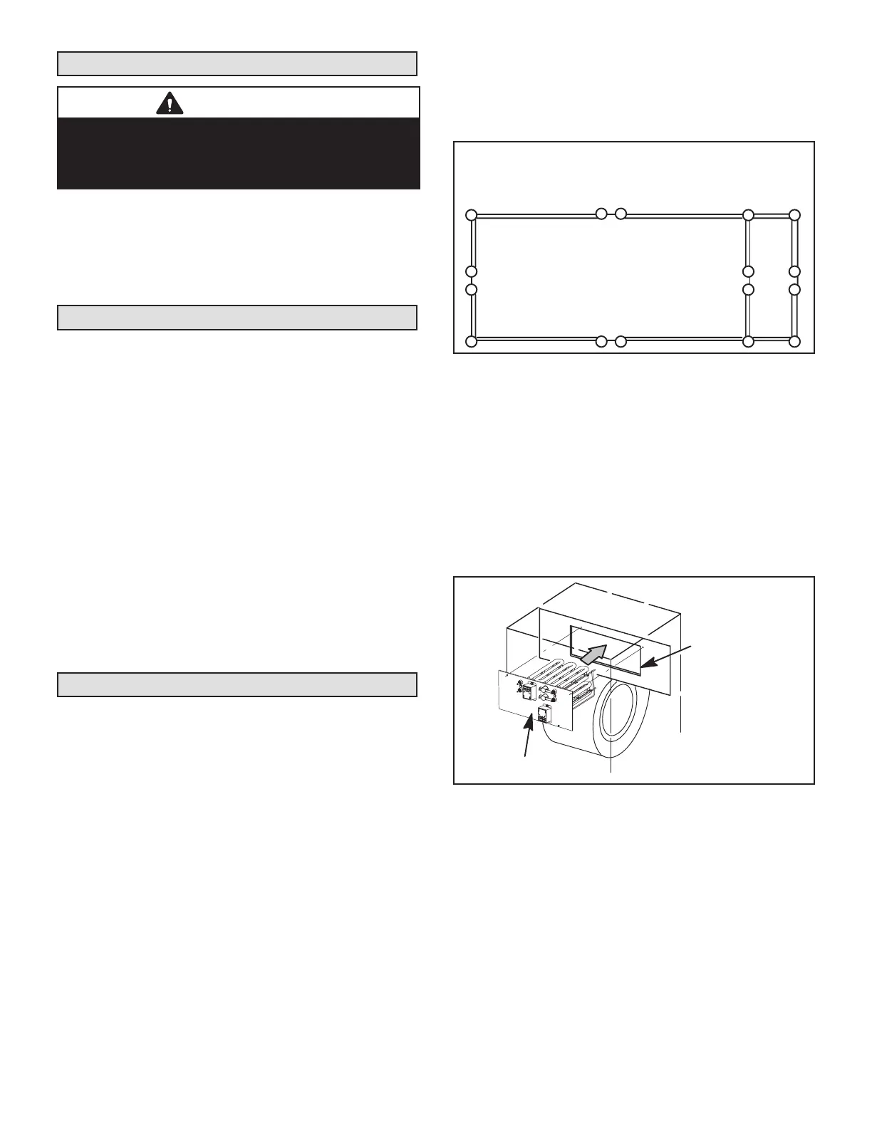
6 - Slide the electric heat section into the air handler
as illustrated in gure 3. Be careful that the heating
elements do not rub against the sheet metal opening
when they slide into the air handler. The hole(s) on
each side of the heater line up with holes in the air
handler control box. Secure the electric heater into
place with the screws that are provided in the bag
assembly.
ELECTRIC HEAT
KNOCKOUT SECTION
ELECTRIC HEAT
FIGURE 3. Electric Heat Section Installation
7 - Reinstall the air handler control L-bracket mounting
plate by lifting it back in place. Tighten the two
screws to secure in place.
8 - Plug the 9-pin connector from the electric heat
section onto the air handler control 9-pin receptacle
as illustrated in gure 1, detail B.
 Loading...