Page 19
(BACKSIDE)
REMOVE PAPER COVERING
FIGURE 10. Remove Paper Cover
IMPORTANT
Conrm air tight seal between breaker cover and air
handler access panel. Apply a thin silicone bead to the
adhesive back seat to ensure air tight seal.
Failure to seal circuit breaker cover will allow warm
moist air to be pulled into control panel which can create
condensation to form on the circuit breaker and other
electrical components within the control panel.
FIGURE 11. Typical Circuit Breaker Cover Installation
Air Handler Speed Connections
When using the electric heat sections with air handler
units, you must adjust the air handler speed according to
the size of electric heat and air handler unit. Air handler
speed tap for electric heat in upow and horizontal
position is medium. For downow it is high speed.
See specic air handler installation instructions for air
handler speed adjustment procedure and location.
1 - Set the thermostat above room temperature.
2 - Check the heat pump and the heat section for
normal operation.
3 - Set the thermostat to desired setting.
4 - Ax the wiring diagram sticker to air handler scroll,
aligned with circuit breaker unit wiring diagram
sticker.
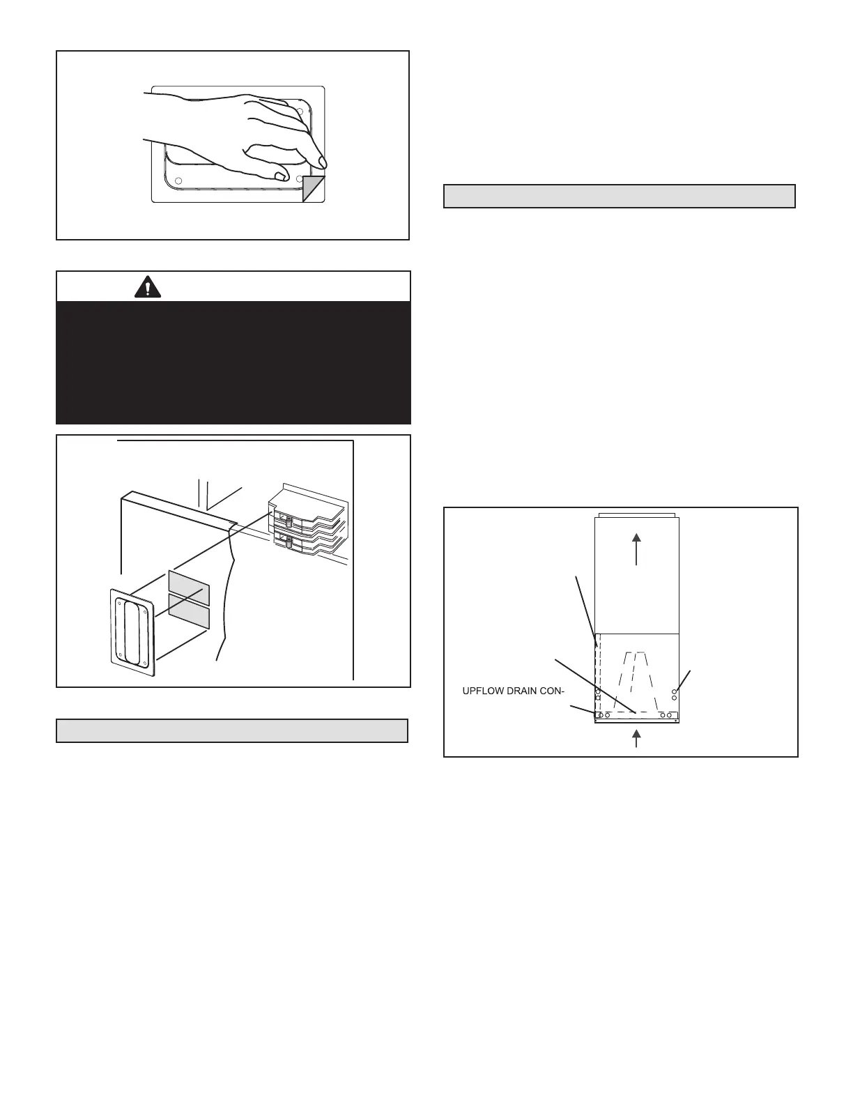
Conguration Modication
UPFLOW APPLICATION
1 - The air handler must be supported on the bottom
only and set on solid oor or eld-supplied support
frame. Securely attach the air handler to the oor or
support frame.
2 - If installing a unit in an upow application, remove
the horizontal drain pan. IMPORTANT - The
horizontal drain pan is not required in upow
air discharge installations; its removal provides
the best eciency and air ow.
3 - Place the unit in the desired location and slope unit
as previously mentioned. Connect return and supply
air plenums as required using sheet metal screws.
4 - Install units that have no return air plenum on a
stand that is at least 14" from the oor. This will
allow proper air return.
HORIZONTAL DRAIN PAN
IMPORTANT! REMOVE PAN
FOR BEST EFFICIENCY
AND AIR FLOW.
UPFLOW
DRAIN PAN
NECTIONS (BOTH
SIDES; USE ONE SIDE
OR OTHER)
HORIZONTAL DRAIN
CONNECTIONS
(BOTH SIDES; NOT
USED)
FIGURE 12. Upow Conguration
 Loading...