Page 9
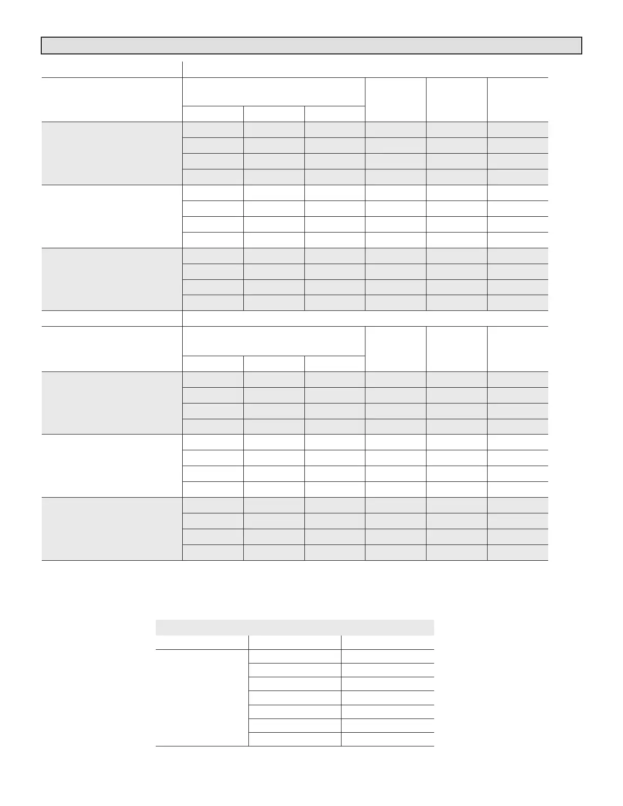
TABLE 4. CBA25UHV Thermostat and Two-Stage Outdoor Unit Operating Sequence
Operating Sequence System Demand System Response
System
Condition
Step
Thermostat Demand Relative Humidity
pressor
Air
Handler
CFM
(COOL) CommentsY1 Y2 O G W1 W2 Status D
NO CALL FOR DEHUMIDIFICATION
Normal Operation
- Y1
1 On On On Acceptable 24 VAC Low 70%
Compressor and indoor air handler follow
thermostat demand
Normal Operation
- Y2
2 On On On On Acceptable 24 VAC High 100%
Room Thermostat Calls for First-Stage Cooling
BASIC MODE (only active on a Y1 thermostat demand)
Normal Operation 1 On On On Acceptable 24 VAC Low 70%
gizes D on a call for dehumidification
Dehumidification
Call
2 On On On On Demand 24 VAC High
60%/65%
70%*
PRECISION MODE (operates independent of a Y1 thermostat demand)
Normal Operation 1 On On On Acceptable 24 VAC Low 70%
midity is greater than set point
Dehumidification
Call
2 On On On On Demand 0 VAC High
60%/65%
70%*
Dehumidification
Call ONLY
1 On On On On Demand 0 VAC High
60%/65%
70%*
midity setpoint by allowing the room
stat setpoint**
Room Thermostat Calls for First- and Second-Stage Cooling
BASIC MODE (only active on a Y1 thermostat demand)
Normal Operation 1 On On On On Acceptable 24 VAC High 100%
gizes D on a call for dehumidification
Dehumidification
Call
2 On On On On Demand 0 VAC High
60%/65%
70%*
PRECISION MODE (operates independent of a Y1 thermostat demand)
Normal Operation 1 On On On On Acceptable 24 VAC High 100%
midity is greater than set point
Dehumidification
Call
2 On On On On Demand 0 VAC High
60%/65%
70%*
Dehumidification
Call ONLY
1 On On On On Demand 0 VAC High
60%/65%
70%*
midity setpoint by allowing the room
stat setpoint**
Jumpers at indoor unit with a two-stage outdoor unit
With Condensing unit - Y2 and R to O
With Heat Pump - none
* During dehumidification, cooling air handler speed is as follows: 70% of COOL cfm for 018, 024, 030; 65% for 036; 60% for 042, 048 and 060 units.
** Thermostat will maintain the room temperature up to 2°F (1.2°C) cooler than the room thermostat setting in precision mode.
HEAT JUMPER
The HEAT jumper is used to determine CFM during elec-
tric heat operation only. These jumper selections are acti-
vated only when W1 is energized.
DELAY JUMPER
The DELAY jumper is used to set the specic motor fan
operation during cooling mode. Depending on the appli-
cation, one of four options may be chosen by moving the
jumper to the appropriate set of pins.
#1 Pins Jumpered
A- Motor runs at 100% until demand is satised.
B- Once demand is met, motor ramps down to stop.
OFFOFF
100% CFM
COOLING
DEMAND
#2 Pins Jumpered
A- Motor runs at 100% until demand is satised.
B- Once demand is met, motor runs at 100% for 60 sec-
onds.
C- Motor ramps down to stop.
OF
OFF
100% CFM
100% CFM
(60 seconds)
COOLING DEMAND
#3 Pins Jumpered
A- Motor runs at 82% for approximately 7-1/2 minutes. If
demand has not been satised after 7-1/2 minutes.
B- Motor runs at 100% until demand is satised.
C- Once demand is met, motor ramps down to stop.
OFF
A
82%CFM
100% CFM
COOLING DEMAND
7 1/2 MIN
#4 Pins Jumpered
A- Motor runs at 50% for 30 seconds.
B- Motor then runs at 82% for approximately 7-1/2 min-
utes. If demand has not been satised after 7-1/2 minutes,
C- Motor runs at 100% until demand is satised.
 Loading...