Page 9
Make sure the liquid line and suction line entry points are
sealed with either the provided exible elastomeric ther-
mal insulation, or eld provided material (e.g. Armaex,
Permagum or equivalent). Any of the previously men-
tioned materials may be used to seal around the main and
auxiliary drains, and around open areas of electrical inlets.
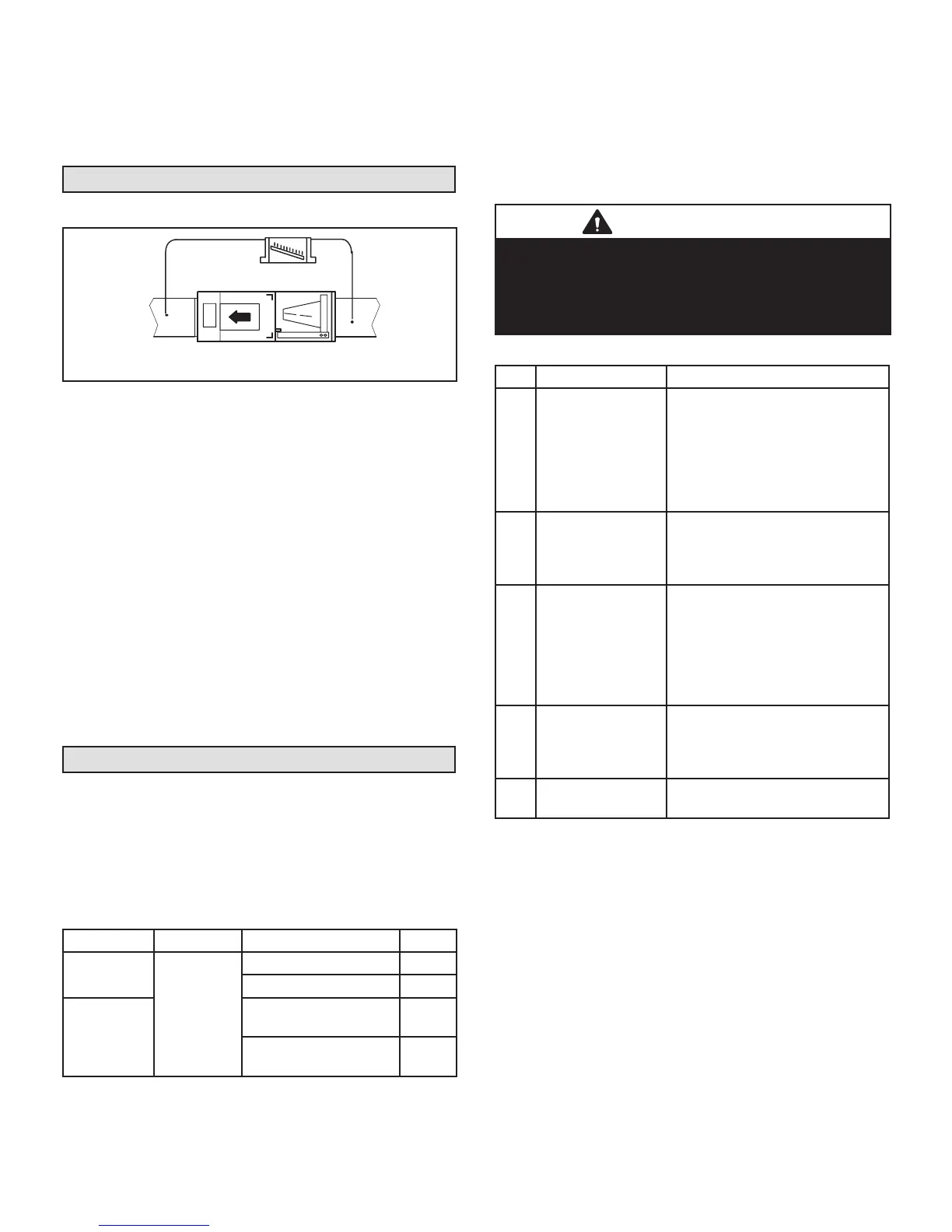
Measuring Static Pressure
1 - Measure tap locations as shown in gure 9.
MANOMETER
SUPPLY
RETURN
UNIT SHOWN IN
HORIZONTAL DISCHARGE LEFT POSITION
FIGURE 9. Static Pressure Test
2 - Punch a 1/4ʺ (6mm) diameter hole in supply and
return air plenums. Insert manometer hose ush
with inside edge of hole or insulation. Seal around
the hose with permagum. Connect the zero end of
the manometer to the discharge (supply) side of
the system. On ducted systems, connect the other
end of manometer to the return duct as above. For
systems with non-ducted returns, leave the other
end of the manometer open to the atmosphere.
3 - With only the blower motor running and the
evaporator coil dry, observe the manometer reading.
Adjust blower motor speed to deliver the air desired
according to the job requirements.
4 - For best air performance external static pressure
drop must not exceed 0.5" W.C. (1.2 kPa). Refer to
blower data tables for CFM and external static.
5 - Seal around the hole when the check is complete.
Adjusting Blower Speed
MOTOR SPEED TAPS
NOTE – Motor is programmed for a 45-second delayed
OFF on all speed taps except TAP #1 (continuous fan
speed).
Table 4 lists the recommended factory blower speed tap
selections for CBA27UH series units.
TABLE 4. Recommended Blower Speed Tap Selection
Operation CBA27UHE Outdoor Unit Tap
Cooling
ALL SIZES
Air conditioner 3
Heat pump 3
Heating*
Air conditioner with
electric heat only
4
Heat pump with electric
heat
4
*Minimum setting for heat
These settings are for nominal tonnage match-ups with
the CBA27UHE units. When matched with other sizes, it is
recommended that the CFM be adjusted to approximately
400 CFM per ton.
To change blower motor speed tap remove the speed tap
from Y2 on the terminal strip and insert the desired speed
tap. Use the Blower Data tables on pages 10 and 11 for
the desired CFM setting.
IMPORTANT
The high-efciency programmable motor features
programmed electronic braking. The integral control
brakes the motor near the end of the supply blower
operation, allowing the motor to maintain a more
controlled ramping shut-down.
TABLE 5. Motor Speed Taps
Tap Operation Remarks
1
Continuous or
low-speed fan (for
two-speed heat
pumps or AC units)
Continuous fan speed is
energized (24volt input to G)
when either G or Y1 has a 24
volt signal (24 volt input from
Y1 passes through the room
thermostat’s Fan Automatic
contacts to the G terminal).
2
Low-speed
operation on
high-static
system
CFM set at 1/2 ton less than
nominal of unit (e.g. 3-ton set at
1000 CFM).
3
Cooling speed
setting
CFM set at 400 cfm per nominal
ton at ARI minimum static
allowed, as follows:
1.5 to 2.0 ton - 0.10
2.5 to 3.5 ton - 0.15
4 to 5 ton - 0.20
4
Heat pump with
electric heat
CFM set at 400 cfm per nominal
ton at .4 static. Energized when
electric heat element has a call
for heat.
5
High-static
applications
CFM set at 400 cfm per nominal
ton at .8 static.
 Loading...