Page 28
VI−CONFIGURATION MODIFICATIONS
CBX32MV unit may be installed in the upflow, downflow,
horizontal right-hand discharge or horizontal left-hand
discharge orientation.
The units come from the factory ready for upflow or
horizontal right-hand discharge installation. If the unit
needs to be modified from its original configuration, use the
following procedures. All procedures assume the unit has
not been modified from the factory.
A−Disassembly of CBX32MV Cabinet
For tight applications where a modular design is an
advantage, the CBX32MV unit can be easily disassembled
and reassembled. By removing four screws, the top blower
section lifts off so the unit is in two parts. To disassemble the
CBX32MV, use the following procedure.
1− Remove the two black screws located just above the
seam in the top half of the unit.
2− Remove the front access panel and remove the two
screws on the inside of the top half of the cabinet on
both sides.
3− Lift the top section apart from the bottom section.
4− To lighten the cabinet for lifting, the blower and coil
assemblies can also be removed.
5− Reassemble once the cabinet is in place.
B−Upflow Application
1− Discard drip shields, if applicable. The shields are used
for downflow applications only and are located with the
foam pads on top of unit.
2− For best efficiency and air flow, the horizontal drain
pan should be removed from units in upflow
configurations.
3− After removing horizontal drain pan, place unit in
desired location. Set unit so that it is level. Connect
return and supply air plenums as required using sheet
metal screws. See figure 18.
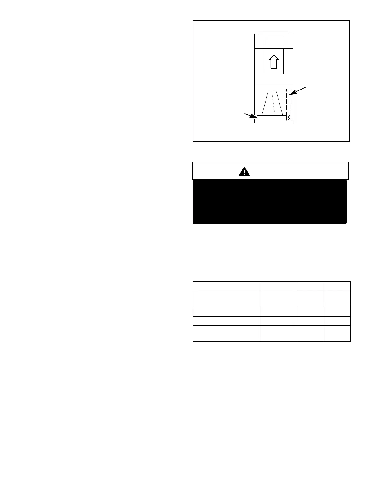
FIGURE 18
UPFLOW CONFIGURATION
*FOR OPTIMUM PERFORMANCE,
REMOVE HORIZONTAL DRAIN PAN.
HORIZONTAL
DRAIN PAN*
UPFLOW/
DOWNFLOW
DRAIN PAN
C−Downflow Application
WARNING
If electric heat section with circuit breakers
(ECB29) is applied to downflow CBX32MV unit, the
circuit breakers must be rotated 180_ to the UP
position. See ECB29 installation instructions for
more details.
1− Remove drip shields shipped with the foam pads from
top of unit. The shields are used for downflow
applications only and may need to be field fabricated if no
longer with unit. See table 14 for drip shields used.
2− Remove coil assembly from unit.
3− Remove horizontal drain pan. See figure 19.
TABLE 14
Unit
Part No. Length Width
CBX32MV−018/024
Not
Required
N/A N/A
CBX32MV−024/030 LB−74274 15.875 4.6718
CBX32MV−036 LB−74272 17.875 4.6718
CBX32MV−048, −060,
−068
LB−89864 19.875 4.6718

 Loading...