Page 6
• Sends discharge temperature status message when
operating in EVENHEAT mode.
• Sends discharge air sensor temperatures to be dis-
played on the Air Handler Control when operating in
EVENHEAT mode
The discharge air sensor should be mounted downstream
of the electric heat elements and indoor air handler as il-
lustrated in gure 1, detail C. It must be placed in a lo-
cation with unobstructed airow, where other accessories
(such as humidiers, UV lights, etc.) will not interfere with
its accuracy
Electrical Connections
IMPORTANT
USE COPPER CONDUCTORS ONLY
NOTE - Refer to the nameplate on the air handler unit
for minimum circuit ampacity and maximum overcurrent
protection size.
The air handler units are provided with openings to be
used with 1-1/2 inch trade size (1-31/32 inch diameter)
conduit.
Select the proper supply circuit conductors in accordance
with tables 310-16 and 310-17 in the National Electric
Code, ANSI/NFPA No. 70 or tables 1 through 4 in the Ca-
nadian Electric Code, Part I, CSA Standard C22.1.
AIR HANDLER CONTROL 9-PIN CONNECTOR
Wiring connections between the air handler and the
ECB38 electric heat section are made with an eight wire
harness. See table 1 for wire designations.
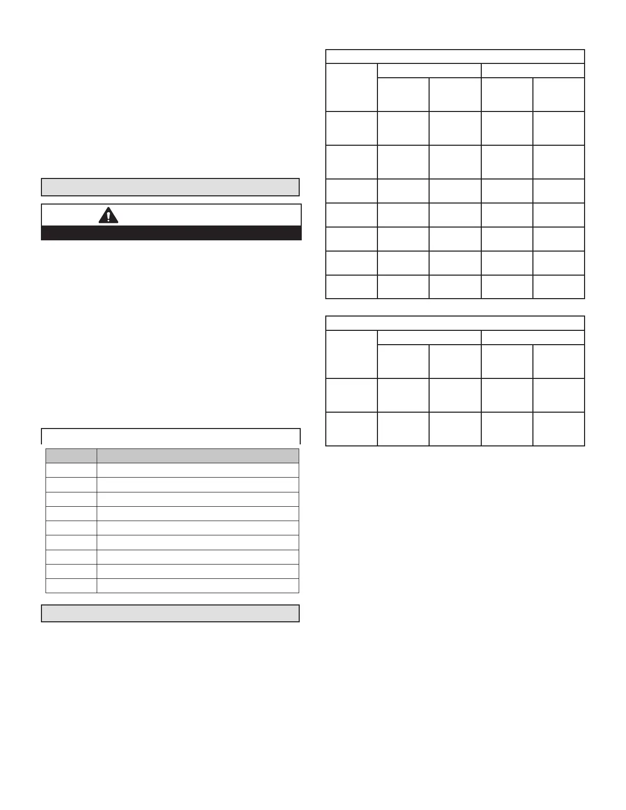
TABLE 1. Electric Heat Connectors
Position Function / Description
1 Heat stage 1 relay coil
2 Heat stage 2 relay coil
3 Relay coil return
4 Heat stage 3 relay coil
5 Heat stage 4 relay coil
6 Heat stage 5 relay coil
7 L1 230VAC supply from heater kit
8 L2 230 VAC supply from heater kit
9 Not Used
Unit Start-Up
1 - Use speed tap selection charts in tables 2 and 3 to
set air handler blower speed.
TABLE 2. Recommended Blower Speed Tap Selection
SPEED TAP SELECTION
BLOWER
COIL
COOL HEAT
AC HP
AC WITH
ELECTRIC
HEAT
HP WITH
ELECTRIC
HEAT
-018
COOL
PIN #2
COOL
PIN #2
HEAT
PIN #4
minus
HEAT
PIN #4
minus
-024
COOL
PIN #3
COOL
PIN #3
HEAT
PIN #4
minus
HEAT
PIN #4
minus
-030
COOL
PIN #3
COOL
PIN #3
HEAT
PIN #3
HEAT
PIN #3
-036
COOL
PIN #3
COOL
PIN #3
HEAT
PIN #3
HEAT
PIN #3
-042
COOL
PIN #3
COOL
PIN #3
HEAT
PIN #3
HEAT
PIN #3
-048
COOL
PIN #2
COOL
PIN #2
HEAT
PIN #2
HEAT
PIN #2
-060
COOL
PIN #3
COOL
PIN #3
HEAT
PIN #3
HEAT
PIN #3
TABLE 3. Recommended Blower Speed Tap Selection
MIX MATCH SPEED TAP SELECTION
BLOWER
COIL
COOL HEAT
AC HP
AC WITH
ELECTRIC
HEAT
HP WITH
ELECTRIC
HEAT
-042 with
2-ton HP
COOL
PIN #1
minus
COOL
PIN #1
minus
HEAT
PIN #1
minus
HEAT
PIN #1
minus
-048 with
3-ton HP
COOL
PIN #1
minus
COOL
PIN #1
minus
HEAT
PIN #1
minus
HEAT
PIN #1
minus
2 - Restore power to the unit with room thermostat set
to OFF.
3 - Unit can be congured in either Standard Heat or
EVENHEAT Mode. See Conguring/Detecting Heat
Section ow diagram on page 12 for set up.
4 - Afx the wiring diagram sticker to blower scroll
aligned with CB unit wiring diagram sticker.
5 - The air handler access panels are factory supplied,
and they have a patch plate over the circuit breaker
opening. Remove the circuit breaker patch plate
from the air handler access panel.
6 - Replace the air handler compartment access cover.
7 - Choose the appropriately sized adhesive-backed
circuit breaker seal and remove any perforated
sections (if needed). Apply the seal to the outside of
the air handler access panel so that the seal is snug
around the circuit breakers (see gure 4).
8 - Break the patch plate for the specic size of electric
heat unit / air handler unit that you are installing as
illustrated in gure 5. Discard the unused piece of
patch plate.
9 - Secure the patch plate on the air handler access door.
10 - Set the thermostat to desired setting.
 Loading...