• 28 • Installation - Operation - Maintenance manual (IOM) • AIR COOLED CHILLERS & SPLIT UNITS - 0105-E
6.2.3 - Automatic sequences
6.2.3.1 - Starting sequence:
- Press the unit start switch, the power light will come on ; The control circuit cannot be energised if there is no power
supply to the main power circuit.
- Depending on the demand for cooling, the control thermostat authorises start up of the compressor(s), which
takes place in sequence. The compressor run indicating lights come on.
6.2.3.2 - Regulator stoppage sequence :
When the cooling load starts decreasing from its maximum value, the multi-stage control thermostat shuts
down successive stages depending on the progressive reduction in return chilled liquid temperature.
Depending on machine equipment, staged reduction consists either in shutting down a compressor or activation
of a compressor capacity reducer. This continues until the unit shuts down completely through action of the
regulator. The compressor regulation stoppage lights come on.
6.2.3.3 - Safety shutdown sequence :
If a default occurs on a circuit, it is detected by the appropriate safety device, (high pressure overshoot, loss of oil
pressure, motor protection, etc...) The relay in question initiates unconditional stoppage of the compressor on that
circuit and the safety stoppage indicating light comes on.
Some defaults give rise to immediate stoppage of the entire unit :
- Tripped flow switch,
- Tripped antifreeze thermostat
- ...etc....
In cases other than that of manually reset safety devices, starting up of the circuit or the machine takes place
automatically once the default has been cleared.
6.2.3.4 - Loss of power supply :
There are no problems restarting the machine after a loss of power supply of short duration (up to about one hour).
If loss of power supply lasts longer than this, when power supply is resumed set the unit to «OFF» with the
compressor crankcase heaters activated for as long as it takes to bring sump oil back up to temperature, then restart
the unit.
6.2.3.5 - Pressostatic water valve :
This device is available as an option for low capacity water cooled condensing units (MCW)
The pressostatic water valve should be installed on the condenser outlet. It enables water flow through the heat
exchanger to be varied so as to maintain condensing pressure at an appropriate value.
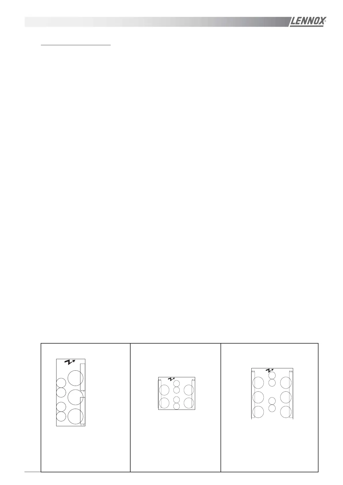
6.2.3.6 - Fan motor control:
ECOLOGIC - Fans electrical box labelling.
2
M33
Cp.2
M32
1
Cp.1
Cp.1
Cp.2
M31
2 V
1950
1950
C1
C2
VENT1/C1
VENT1/C2
FR/C1
VENT C1/C2
Cp.2
Cp.1
Cp.1
C
Cp.2
C2
M33
M34
M31
M32
WA/RA 230D
WA/RA 200D
C2C
2 V2 V
2800
2800
VENT1/C1
FR/C1
VENT2/C1
VENT1/C2
FR/C2
VENT2/C2
Cp.2
Cp.1
Cp.1
Cp.2
C1
2 V
M32
M33
C2
4200
M31
C1
2 V
M36
M35
C2
WA/RA 300D
M34
4200
VENT1/C1
FR/C1
VENT2/C1
VENT3/C1
VENT1/C2
FR/C2
VENT2/C2
VENT3/C2
OPERATION
(except LN)
(except LN)
(except LN)
(except LN)
(except LN)
 Loading...