Page 13
EL18XCV Thermostat Control Options
Thermostat Type Indoor Unit Type
Qty. of
Wires to
EL18XCV
EL18XCV
Terminal Strip
Connections
Unit Operation
Field Wiring
Diagram
S30 Communicating
Thermostat
Comunicating Gas
Furnace or Air Handler
4 R, I+, I-, C
Fully Communicating Variable Capacity
Operation Based Upon Thermostat Demand
Figure 13
Conventional 24VAC
2-Stage Cooling
Thermostat
(non-communicating)
Any Furnace or Air
Handler
(non-communicating
or communicating)
4 R, C, Y1, Y2
Full Variable Capacity Operation Controlled
by EL18XCV Unitary Control Using Suction
Pressure
Figure 14
Conventional 24VAC
Single-Stage Cooling
Thermostat
(non-communicating)
Any Furnace or Air
Handler
(non-communicating
or communicating)
3
R, C, Y1
(Jumper Y1 to Y2)
Full Variable Capacity Operation Controlled
by EL18XCV Unitary Control Using Suction
Pressure
Figure 14
Refer to the unit nameplate for minimum circuit ampacity,
and maximum fuse or circuit breaker (HACR per NEC).
Install power wiring and properly sized disconnect switch.
NOTE - Units are approved for use only with copper
conductors. Ground unit at disconnect switch or
connect to an earth ground.
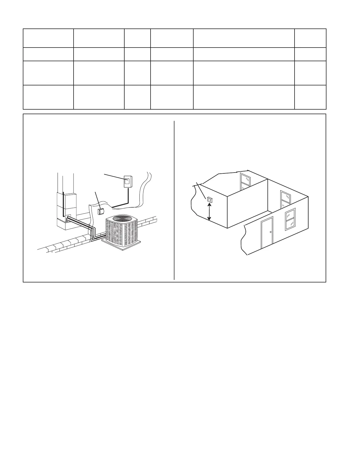
SIZE CIRCUIT AND INSTALL SERVICE
DISCONNECT SWITCH
NOTE - 24VAC, Class II circuit connections are
made in the control panel.
Install room thermostat (ordered separately) on an
inside wall approximately in the center of the conditioned
area and 5 feet (1.5m) from the floor. It should not be
installed on an outside wall or where it can be affected
by sunlight or drafts.
THERMOSTAT
5 FEET
(1.5M)
INSTALL THERMOSTAT
SERVICE
DISCONNECT
SWITCH
MAIN FUSE
BOX/BREAKER
PANEL
FIGURE 11
 Loading...