Do you have a question about the Lennox G1D91BT and is the answer not in the manual?
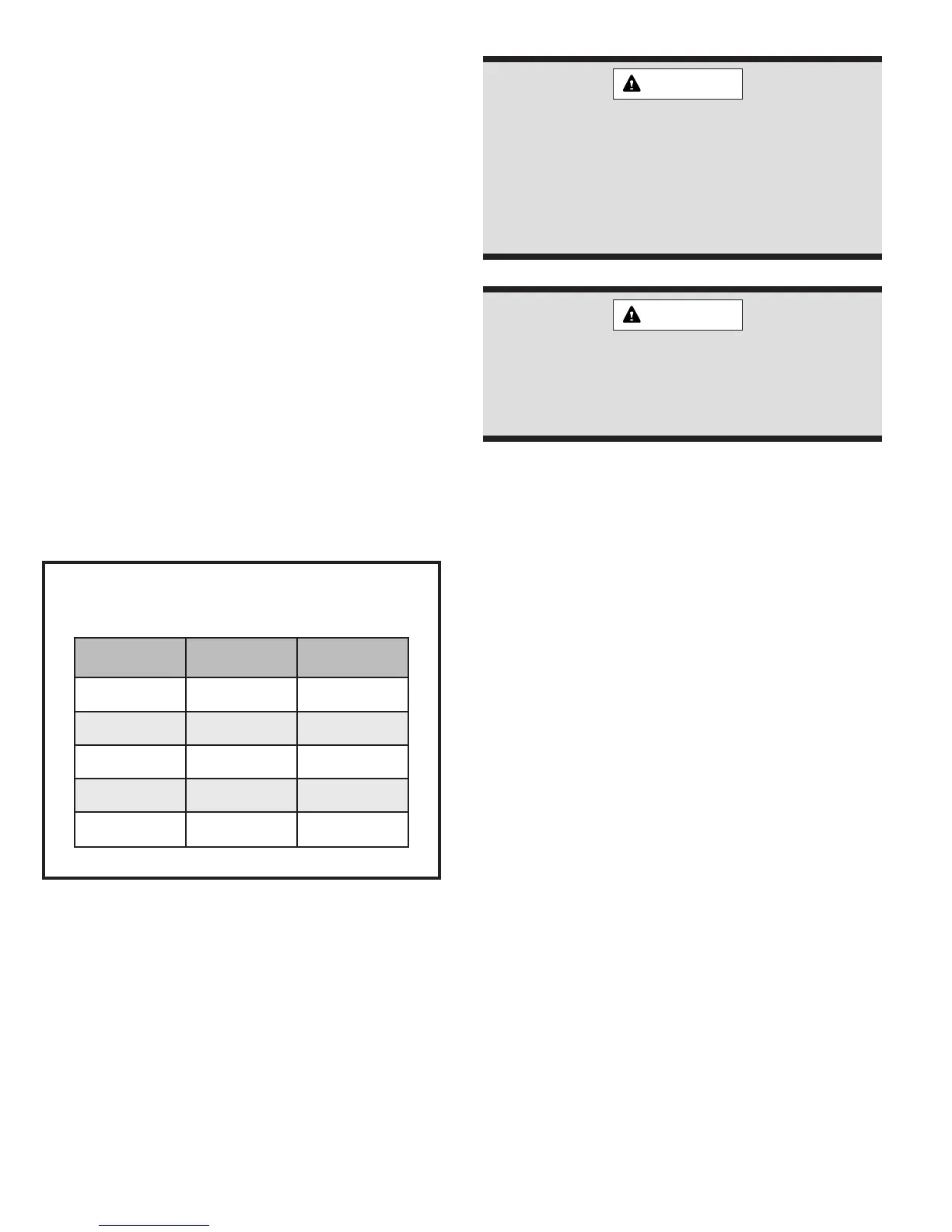
Warnings regarding improper installation, adjustment, alteration, service, or maintenance of the furnace.
Warning against storing combustible materials near the furnace, vent pipe, or warm air ducts.
This furnace is explicitly not approved for installation in a mobile home environment.
Installation must adhere to NFPA, National Fuel Gas Code, NEC, CSA standards, and local codes.
Essential safety rules and precautions that must be followed during the installation of this furnace.
Specific installation requirements for Massachusetts, including licensed professionals and flexible connector length limits.
Guidelines for furnace placement, certification compliance, and suitability for various installation locations.
Details for installing the furnace in a horizontal orientation, including securing the upper door.
Considerations for choosing a furnace location, focusing on atmosphere, water protection, and unit levelness.
Cautionary note on protecting the condensate system from freezing temperatures and insulation needs.
Recommendations for installing the furnace in utility rooms or closets for improved accessibility and maintenance.
Specific requirements for garage installations, including burner height and physical protection.
Prohibition on using the furnace for temporary heating in construction sites due to potential damage from environmental factors.
Table specifying minimum clearances required between the furnace and combustible materials for safe operation.
Guidelines on suitable flooring materials for furnace installation, prohibiting direct placement on carpeting or tile.
Essential requirements for providing adequate combustion and ventilation air to ensure safe and efficient furnace operation.
Air supply requirements for furnaces installed in unconfined spaces, assuming sufficient infiltration.
Detailed air supply requirements for furnaces installed in confined spaces, including specific opening sizes and locations.
Discussion on how contaminated combustion air can affect furnace safety and performance, recommending outdoor air.
List of common substances found in building environments that may necessitate using outdoor air for combustion.
Explanation of how high efficiency is achieved through condensation removal and the importance of proper venting considerations.
Overview of direct vent (two-pipe) and non-direct vent (one-pipe) installation methods for the furnace.
Instructions for correctly installing the inlet air restrictor plate for non-direct vent furnace configurations.
Guidance on installing the flue pipe screen at the vent termination to prevent debris entry.
Guidelines for supporting the furnace vent piping to prevent sagging and ensure structural integrity.
Requirements for installing vent pipes through building penetrations, adhering to codes like NFC and ANSI.
Recommendations for insulating vent pipes with Armaflex or similar materials in unconditioned or cold environments.
Details on approved materials for vent piping, including specifications from ANSI and ASTM.
Critical limitations on connecting Category IV furnaces to specific vent types, chimneys, or common venting systems.
Information on the availability and use of the concentric vent kit for direct vent installations.
Tables providing guidance on sizing vent and air intake pipes based on length and number of elbows.
Restrictions on where horizontal vent terminals can be terminated to prevent condensate issues or hazards.
Clearance specifications for direct vent sidewall terminals in the United States, varying by location and appliance size.
Clearance specifications for direct vent sidewall terminals in Canada, varying by location and appliance size.
Clearance specifications for non-direct vent sidewall terminals in the United States, varying by location and appliance size.
Clearance specifications for non-direct vent sidewall terminals in Canada, varying by location and appliance size.
Diagram and instructions for horizontal direct vent installations, including pipe slope and air intake.
Diagram and instructions for vertical direct vent installations, including pipe height and air intake.
Important cautions for direct vent systems, including self-support and avoiding restrictor plates.
Diagram and instructions for horizontal non-direct vent installations, including pipe slope and air intake.
Diagram and instructions for vertical non-direct vent installations, including pipe height and air intake.
Key cautions for non-direct vent installations, emphasizing restrictor plate use and vent system support.
Diagram illustrating horizontal direct vent installation with horizontal airflow, showing clearances and pipe runs.
Diagram illustrating horizontal direct vent installation with vertical venting, showing clearances and pipe runs.
Diagram illustrating horizontal non-direct vent installation with horizontal airflow, showing clearances and pipe runs.
Diagram illustrating horizontal non-direct vent installation with vertical venting, showing clearances and pipe runs.
Methods for achieving proper vent pitch in horizontal installations with limited space above the unit.
Critical procedure for testing venting systems to prevent carbon monoxide poisoning, detailing specific steps and checks.
Recommendations for routing condensate drains to prevent freezing and ensure proper disposal.
Instructions for installing the condensate drain line for furnaces in an upflow configuration.
Procedure for installing the condensate trap assembly for horizontal installations with right-to-left airflow.
Final steps for completing the condensate drain installation in upflow configurations, including hose connections.
Procedure for installing the condensate trap assembly for horizontal installations with left-to-right airflow.
Final steps for completing the condensate drain installation in horizontal configurations, including hose connections.
Alternate method for installing the condensate drain trap assembly in areas with limited clearance beneath the unit.
Instructions for connecting the pressure switch hose to the flue pan for upflow installations.
Procedure for connecting the pressure switch hose for horizontal installations with right-to-left airflow.
Procedure for connecting the pressure switch hose for horizontal installations with left-to-right airflow.
Mandatory requirements for return air supply when furnace ducts serve areas external to the furnace space.
Cautionary advice on placing evaporator coils in the return air path to prevent internal furnace condensation.
Requirement for a removable access panel in the outlet duct when the furnace is not equipped with a cooling coil.
Critical warnings regarding propane conversion, potential overfiring, and carbon monoxide hazards.
Guidelines for installing gas supply piping, ensuring compliance with codes, utility standards, and proper compounds.
Warning concerning maximum gas valve pressure limits and the risks of overfiring and carbon monoxide production.
Procedure for safely checking gas piping connections for leaks using a soap solution, emphasizing the prohibition of open flames.
Essential safety warning for electrical work, stressing power disconnection to prevent shock, fire, or injury.
Requirements for furnace grounding and wiring, adhering to local codes, NEC, and CSA electrical standards.
Instructions for routing the line voltage supply and connecting it through a disconnect and junction box.
Emphasis on correct polarity and secure earth ground connections for proper safety control function.
Guidance on thermostat installation, location selection, and setting the heat anticipator for optimal performance.
Instructions for enabling continuous blower operation by connecting to the designated 'CONT' terminal on the control board.
Details on connecting humidifiers and electronic air cleaners to the blower control board terminals.
Information on twinning furnaces for common control, requiring specific kits and dedicated vent systems.
Step-by-step instructions for installing the furnace filter rack, including panel modifications and fastening.
Table specifying minimum filter area and size requirements based on airflow descriptor for optimal performance.
Essential safety warnings for furnace ignition, including gas leak detection and prohibiting manual burner lighting.
Step-by-step instructions for the initial start-up of the furnace, including thermostat and burner access door procedures.
Detailed steps for manually igniting the main burners and setting the thermostat for desired temperature.
Procedure for safely shutting down the furnace, covering thermostat, power, and gas control settings.
Critical warning to shut off the manual gas valve if overheating occurs or the gas supply fails to stop.
Detailed explanation of the furnace's operation during a heating call, from thermostat input to burner ignition and blower activation.
Description of how the furnace fan operates when set to 'On' mode via the thermostat.
Explanation of the furnace's operation during a cooling call, including delay timers and operational priorities.
Descriptions of the primary and auxiliary limit controls and their roles in furnace operation safety.
Explanation of the interlock switch function that prevents operation when the blower door is removed.
Overview of the blower control board's capabilities, including selectable blower off-delay times and speed adjustment.
Procedure for checking and adjusting the furnace's gas input and manifold pressure to match rating plate specifications.
Detailed steps for measuring manifold pressure using a manometer for natural gas and propane adjustments.
Table providing manifold pressure set points for natural gas and propane at various altitudes.
Procedure for checking temperature rise and adjusting blower speed to meet specified ranges.
Information regarding furnace approval for high altitudes and necessary gas manifold pressure adjustments.
Recommendation for annual inspection by a qualified service technician to ensure optimal heating season performance.
Guidelines for regular checking, cleaning, or replacement of air filters to maintain airflow and prevent motor overheating.
Advice on cleaning blower and induced draft motors periodically to prevent overheating due to dust accumulation.
Instructions for periodic checking of the condensate drain line for blockages to ensure proper furnace operation.
Guidance on observing main burner flames for correct appearance, color, and proper combustion.
Essential visual checks before troubleshooting, including power, gas supply, wiring, and operational sequence.
Explanation of the furnace's built-in self-diagnostic system and how fault codes are displayed via an LED indicator.
Instructions for accessing and clearing stored fault codes using the fault code history button on the control board.
A table detailing LED flash codes and their corresponding fault descriptions for system troubleshooting.
Information on how to order replacement parts, requiring furnace model and serial numbers for accuracy.
List of components included in the control group, such as the gas valve, transformer, and limit switches.
List of components comprising the heat exchanger group, including primary, secondary, and drain pan.
List of components found in the blower group, such as the blower motor, wheel, and housing.
List of components belonging to the burner group, including the gas manifold and main burners.
Catalog of optional accessories for the furnace, such as conversion kits, filter kits, and vent kits.
Diagram illustrating the electrical connections for all furnace components and controls, including safety interlocks.
Schematic diagram detailing the electrical flow and interconnections between furnace components and the control board.


