Page 25
Condensate Piping
This unit is designed for either rightĆ or leftĆside exit of conĆ
densate piping. Condensate drain line should be routed
only within the conditioned space to avoid freezing of conĆ
densate and blockage of drain line. An electric heat cable
should be used where condensate drain is exposed to unĆ
conditioned areas. The following procedure is for all G26
units.
1 - Determine which side condensate will exit the unit.
2 - Connect 1/2" (13mm) plastic pipe plug (provided) in
the unused end of the condensate trap. Install plug so
that it is sealed water tight yet able to be removed. Do
not permanently seal the connection. Teflon tape is
recommended to seal joint. See figure 40.
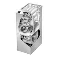
DETAIL OF FLUE TRAP
FLUE TRAP
ASSEMBLY
G26-1 and -2
Models
UNIT CABINET
Y" CONNECTOR
BOOT OR CAP
RUBBER CONNECTOR
HOSE CLAMPS
HOSE BARB
FIGURE 39
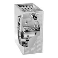
CONDENSATE ASSEMBLY
(For left or right installation)
FIGURE 40
COLD HEADĆ
ER
BOX
NIPPLE
ADAPTER
ADAPTER
NIPPLE
PLUG
BOOT OR CAP
COMBUSTION AIR
BLOWER BRACKĆ
ET
CONDENSATE TRAP
3 - Use the provided adapter (1/2" PVC x 1/2" MPT) and
the nipple (1/2" PVC) to carry drainage outside the
cabinet. If a field substitute is needed, 1/2" CPVC x
1/2" MPT adapter and 1/2" CPVC is acceptable for
use.
4 - Glue nipple to the adapter using the procedures outĆ
lined in the Joint Cementing Procedures" section.
The nipple/adapter assembly should be connected
in a nonĆpermanent manner and must be water tight.
Teflon tape is recommended to seal the joint.
For RightĆHand Side Condensate Exit:
Install the nipple/adapter assembly from the outside
of the cabinet and insert the adapter into the
threaded opening in the condensate trap.
For LeftĆHand Side Condensate Exit:
Insert nipple/adapter assembly from the left hand
side of the cabinet and through the combustion air
blower mounting structure into the threaded openĆ
ing in the condensate trap.
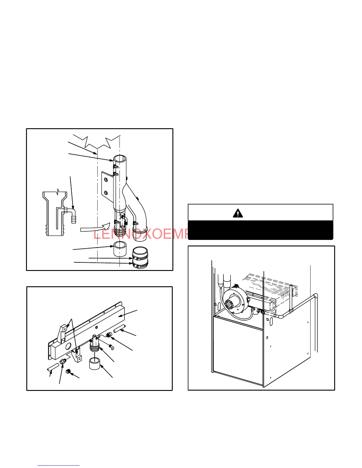
5 - Connect field supplied plumbing to nipple and route to
open drain. Plumbing should be vented to a point higher
than the condensing coil. See figure 41.
CAUTION
Do not use copper tubing or existing copper
condensate lines for drain line.
FIGURE 41
CONDENSATE PLUMBING
(Plumbing must be vented higher than coil.)
 Loading...