G61MPV / Page 9
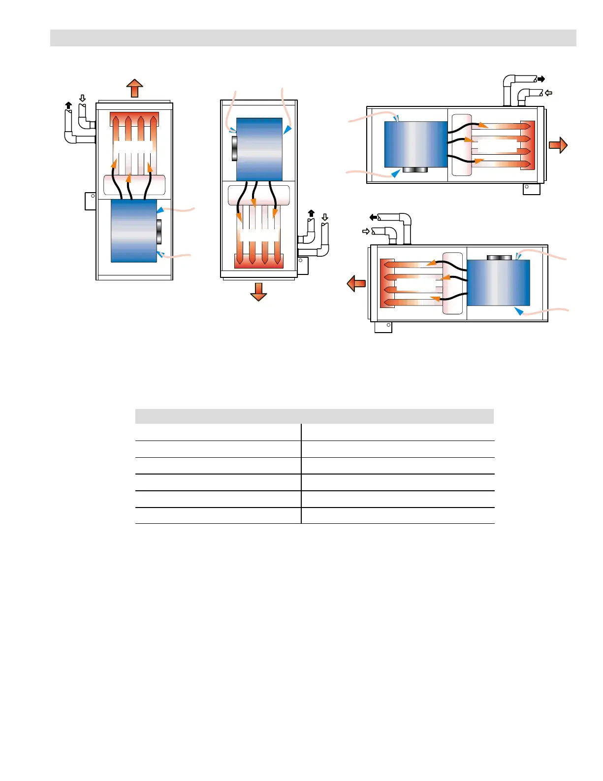
INSTALLATION CONFIGURATIONS
HEAT
EXCHANGER
HEAT
EXCHANGER
HEAT
EXCHANGER
HEAT
EXCHANGER
BLOWER
BLOWER
BLOWER
BLOWER
CONDENSATE
DRAIN
CONDENSATE
DRAIN
CONDENSATE
DRAIN
CONDENSATE
DRAIN
VENT
PIPING
VENT
PIPING
VENT
PIPING
VENT
PIPING
AIR
FLOW
AIR
FLOW
AIR FLOW
AIR FLOW
HORIZONTAL − RIGHT
HORIZONTAL − LEFT
UP−FLOW
DOWN−FLOW
NOTE − On up−flow and down−flow configurations, the vent piping and
condensate drain can be moved to the other side of the unit. Vent piping
and drain must be installed on the same side of the unit with each other
unless optional Condensate Trap Alternate Location Kit (up−flow only) is
used. On horizontal installations the drain must be located at the bottom
and the vent piping at the top.
INSTALLATION CLEARANCES
Sides
1
0 inches (0 mm)
Rear 0 inches (0 mm)
Top/Plenum 1 inch (25 mm)
Front 0 inches (0 mm)
Front (service/alcove) 24 inches (610 mm)
Floor
2
Combustible
NOTE − Air for combustion and supply air ventilation must conform to the methods outlined in American National
Standard (ANSI-Z223.1) National Fuel Gas Code or National Standard of Canada CAN/CGA-149.1, &
CAN/CGA-149.2 Installation Code for Gas Burning Appliances".
NOTE−In the U.S. flue sizing must conform to the methods outlined in current GAMA/A.G.A. venting tables, American
National Standard (ANSI-Z223.1) National Fuel Gas Code or applicable provisions of local building codes. In Canada
flue sizing must conform to the methods outlined in National Standard of Canada CAN/CGA-149.1 and .2.
1
Allow proper clearances to accommodate condensate trap and vent pipe installation.
2
Do not install the furnace directly on carpeting, tile, or other combustible materials other than wood flooring.
 Loading...