2
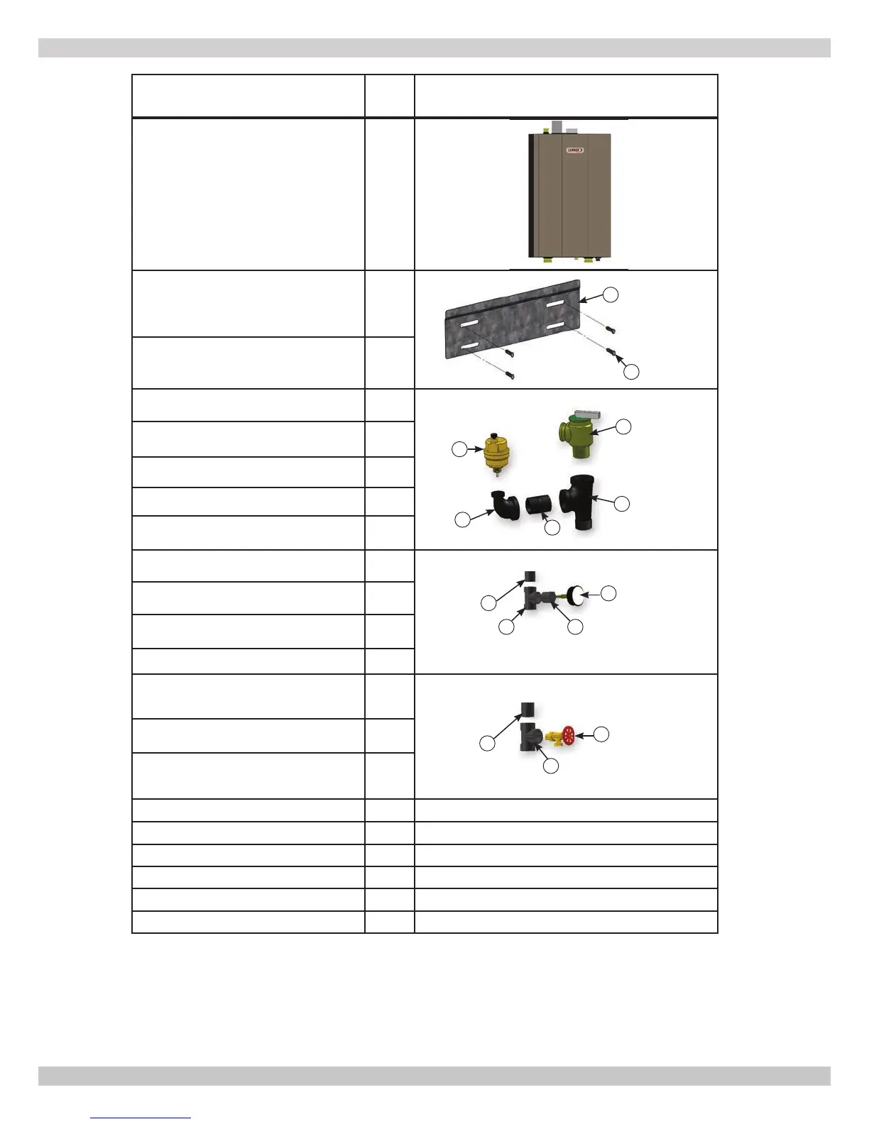
Description
Item
No. Illustration
Fully Assembled Boiler 1
Metal Wall Bracket 2
Lag Bolt, 3/8" x 3" Hex (4 ea) 3
*Safety Relief Valve 4
3/4" Tee 5
3/4" Nipple 6
3/4" x 1/4" Elbow 7
Air Vent 8
**Temperature Pressure Gauge 9
Bushing 3/4" x 1/4" 10
3/4" Tee (Same as No. 11) 11
Nipple 1¼ x 5½ 12
Drain Valve, 3/4" 13
3/4" Tee 14
Nipple 1¼ x 5½ 15
Bushing 7/8" OD, Heyco (2 ea) 16
Used for electrical wire knockouts.
Stopper, Rubber 5/16" (2 ea) 17 Used for packaging holes on back of boiler.
Plastic Plug (2 ea) 18 Used for packaging holes on back of boiler.
Outdoor Sensor 19 Used for measuring outside temperature.
Critical Installation Instruction 20 11" x 17" Page for critical installation issues.
Document Package 21 Includes essential documents.
4
5
6
7
8
2
3
9
10
12
13
14
11
15
VERIFY CONTENTS RECEIVED
* Boiler provided with 30 psig (206 kpa) safety relief valve. Field source safety relief valve if system pressure
greater than 25 psig.
** Boiler provided with 75 psig temperature pressure gauge. Field source temperature pressure gauge if system
pressure greater than 60 psig.
 Loading...