33
8.1 General
Electrically bond boiler to ground in accordance with
requirements of authority having jurisdiction. Refer to:
• USA- National Electrical Code, ANSI/NFPA 70.
• Canada - Canadian Electrical Code, Part I, CSA C22.1:
Safety Standard for Electrical Installations.
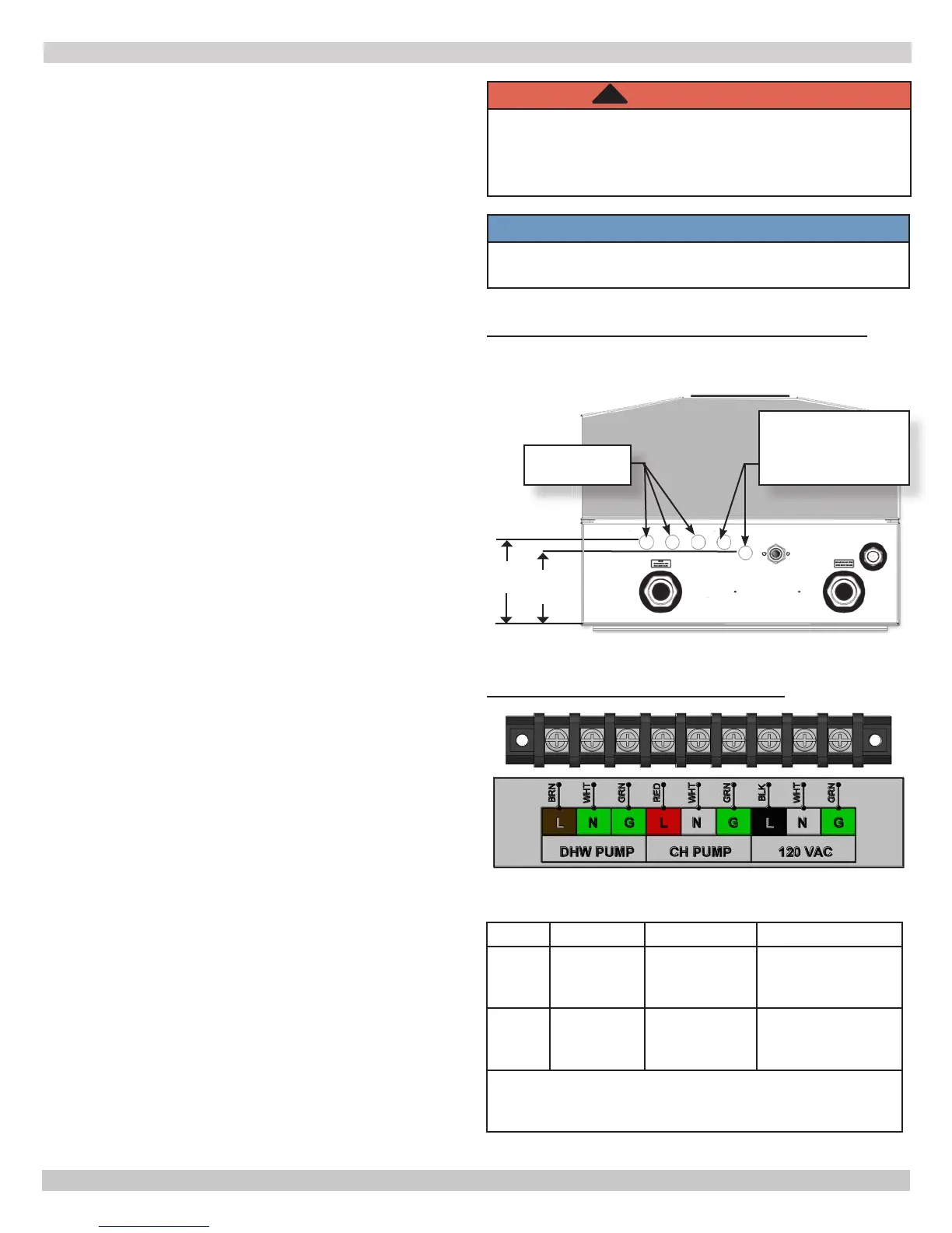
8.2 Electric Knockouts (gure 8-1)
• Five knockouts located on bottom of chassis.
A. Three knockouts located under junction box are
reserved for high voltage wires. Choose connectors
using total diameter of wire bundles.
B. Two knockouts located to right of high voltage
knockouts (outside of junction box) are reserved
for low voltage wiring. Use supplied grommets
when using these knockouts.
8.3 Line Voltage Connections (gure 8-2)
• Boiler
A. Provide individual 120V, 15 amp circuit
(recommended) with fused disconnect or service
switch as required by authority having jurisdiction.
B. Open High Voltage Junction Box (see gures 3-4
and 3-5) to access line voltage terminal strip.
C. Connect 120 VAC circuit to line voltage terminal
strip 120 VAC L,N,G.
• Central Heating Pump, if used.
A. Isolate pump from control module if pump FLA (Full
Load Amps) exceeds maximum allowable current
draw. See Figure 8-3 and Table 11.
B. Connect pump to line voltage terminal strip CH
PUMP L,N,G.
• Domestic Hot Water Pump, if used.
A. Isolate pump from control module if pump FLA
exceeds maximum allowable current draw. See
Figure 8-3 and Table 11.
B. Connect pump to line voltage terminal strip DHW
PUMP L,N,G.
8.4 External Connections (gure 8-4)
• User Interface Terminals
A. Factory wired to USER INTERFACE terminals
B. Optional - Remote mount user interface for
improved access. Use low voltage knockout.
C. Maximum wire length is 100 ft (30m) for 22 ga.
wire, or 150 ft (45m) for 18 ga. wire.
• Argus Link (Multiple boiler applications only)
WARNING
Electrical shock hazard. Turn OFF electrical power
supply at service panel before making electrical
connections. Failure to do so could result in death
or serious injury.
!
FIGURE 8-2 Line Voltage Connections
NOTICE
Wiring diagrams can be found in Section 14 of this
Manual.
FIGURE 8-1 Electric Knockouts Bottom Of Boiler
4½"
(114mm)
5"
(127mm)
High Voltage
Knockouts
Low Voltage Knockouts
(Use supplied
grommets when using
these knockouts)
Front of Boiler
Back of Boiler
8 - ELECTRICAL CONNECTIONS
MBH CH PUMP DHW PUMP NOTE
50
75
100
1 A 1 A
Powered by
Control Board
150
200
10 A 10 A
Powered by
installed 10 Amp
relay
If CH or DHW pump current is more than the maximum
allowable current draw install proper eld sourced relays
as shown in gure 8-3.
Table 11 - Maximum Allowable Current Draw
 Loading...