Harmony III Zoning System / Page 7
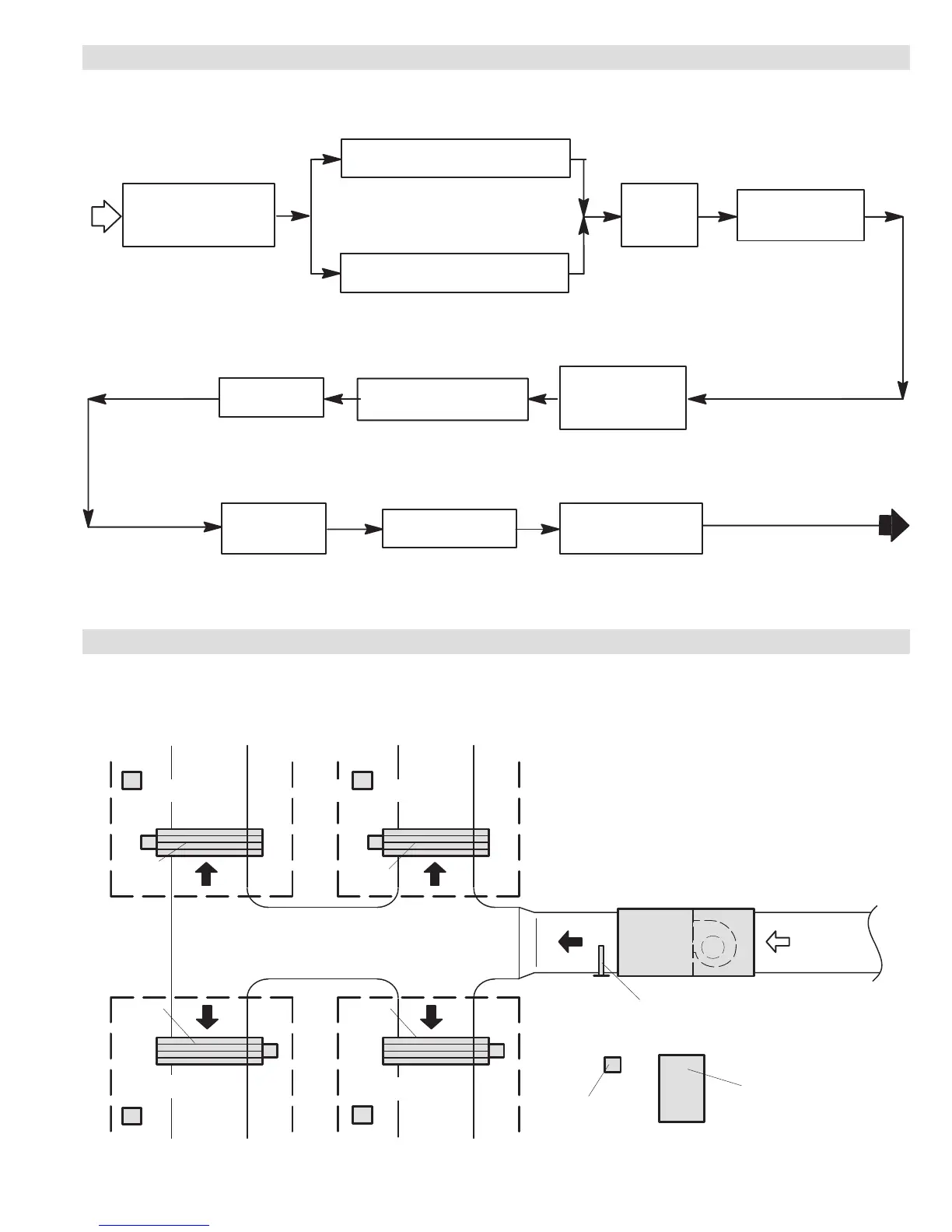
COMPONENT SELECTION
TYPICAL SYSTEM LAYOUT
Pressure Switch
(Heat Pump Applications Only)
(27W13) - R-410A
START
ZONE
THERMOSTAT
One per zone
(See Page 6)
TRANSFORMER
(see page 6 for
selection)
ZONE DAMPERS
at least one per zone
(See Page 6)
Harmony III
Panel with
Discharge
Air Sensor
(X9953)
Lennox Indoor Unit
Equipped with Variable
Speed Blower
(Gas Furnace with Indoor
Coil or Air Handler Unit)
Lennox Single Speed
Air Conditioner or Heat Pump Outdoor Unit
For zone system with two equal size zones
Lennox Two-Stage
Air Conditioner or Heat Pump Outdoor Unit
For two, three or four, zone systems
Balance Point Sensor
(Heat Pump
applications Only)
(56A87)
Defrost Tempering
Switch (Optional for
Dual-Fuel Heat Pump
applications Only)
(67M41)
Humiditrol
®
Zoning
Accessory
(EDA Applications Only)
(39W67)
TRANSFORMER
ZONE
DAMPER
ZONE 2 ZONE 1
ZONE 3ZONE 4
ZONE 4
THERMOSTAT
ZONE 1
THERMOSTAT
ZONE 3
THERMOSTAT
ZONE 2
THERMOSTAT
HEATING/
COOLING
UNIT
ZONE
CONTROL
PANEL
SUPPLY
AIR
RETURN
AIR
ZONE
DAMPER
ZONE
DAMPER
ZONE
DAMPER
DISCHARGE
AIR SENSOR

 Loading...


