EasyManua.ls Logo

Lennox HS27-024 User Manual

Lennox HS27-024
16 pages
To Next Page IconTo Next Page
To Previous Page IconTo Previous Page
Page #4 background image
Page 4
A − Slab Mounting
When you install the unit at grade level, the top of the slab
should be high enough above the grade so that water from
higher ground will not collect around the unit. See figure 3.
Slab should have a slope tolerance away from the building
of 2 degrees or 2 inches per 5 feet (51 mm per 1.5 m).
2 degrees or
2 in. per 5 foot
(51 mm per 1.5 m)
slope tolerance away
from building structure
Slab Mounting
ground level
mounting
slab
building
structure
discharge air
Figure 3
B − Roof Mounting
Install unit at a minimum of 4 inches above surface of the roof.
Care must be taken to ensure weight of unit is properly distrib-
uted over roof joists and rafters. Either redwood or steel sup-
ports are recommended.
Electrical
In the U.S.A., wiring must conform with current local codes
and the current National Electric Code (NEC). In Canada,
wiring must conform with current local codes and the current
Canadian Electrical Code (CEC).
Refer to the furnace or blower coil installation instructions
for additional wiring application diagrams and refer to unit
nameplate for minimum circuit ampacity and maximum
overcurrent protection size.
WARNING
Unit must be grounded in accordance with
national and local codes.
Electric Shock Hazard.
Can cause injury or death.
1. Install line voltage power supply to unit from a properly
sized disconnect switch.
2. Ground unit at unit disconnect switch or to an earth
ground.
NOTE − To facilitate conduit, a hole is in the bottom of
the control box. Connect conduit to the control box us
ing a proper conduit fitting.
NOTE Units are approved for use only with copper
conductors.
24V, Class II circuit connections are made in the low
voltage junction box. Refer to figure 4 for field wiring
diagram.
NOTE − A complete unit wiring diagram is located in
side the unit control box cover.
3. Install room thermostat (ordered separately) on an in-
side wall approximately in the center of the conditioned
area and 5 feet (1.5 m) from the floor. It should not be
installed on an outside wall or where it can be effected
by sunlight, drafts or vibrations.
4. Install low voltage wiring from outdoor to indoor unit
and from thermostat to indoor unit. See figure 5.
Question and Answer IconNeed help?

Do you have a question about the Lennox HS27-024 and is the answer not in the manual?

Lennox HS27-024 Specifications

General IconGeneral
TypeHeat Pump
RefrigerantR-410A
Number of Stages1
Sound Level76 dB
Voltage208/230V
Phase1
Maximum Operating Temperature (Cooling)115°F
Cooling Capacity24000 BTU/h
Heating Capacity24000 BTU/h
Compressor TypeSingle-Stage
Warranty5-Year Limited Parts

Summary

HS27 Outdoor Unit

Setting the Unit

Mounting Options

Electrical

Field Wiring Diagram

Illustrates the electrical connections for the outdoor unit, including compressor and fan wiring.

Refrigerant Piping

Installing Refrigerant Line

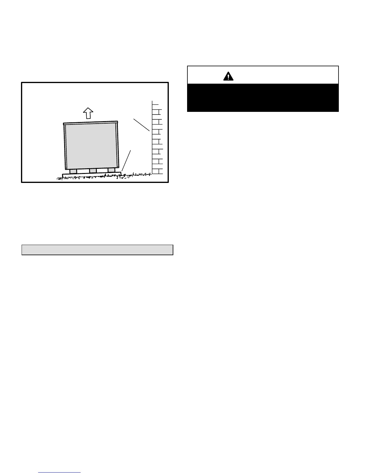
Provides guidelines for isolating refrigerant lines to prevent vibration and noise.

Line Set Isolation

Demonstrates procedures to ensure proper refrigerant line set isolation.

Outdoor Unit Placement

Brazing and System Connections

Brazing Connection Procedure

Provides step-by-step instructions for brazing refrigerant lines to service valves.

Leak Testing

Details the procedure for checking line set and unit connections for refrigerant leaks.

System Diagnostics and Evacuation

Evacuation

Explains the importance of evacuating noncondensables and water vapor from the system.

System Start-Up and Charging

Start-Up Procedures

Details the steps for starting up the unit after installation, including checks and power application.

Charging

Explains how to charge the system with refrigerant based on line set length and unit nameplate.

Charging Using Operating Pressures

Details charging procedures using normal operating pressures and the approach method.

Operation and Maintenance

Start-up and Performance Checklist

Related product manuals