[mm] [mm] [mm] [bar] [N/mm
2
] [N/mm
2
]
10 36 11,2 20,3
12 1,0 14,0 16,2
16 46 19,6 11,6
18 56 21,0 10,8
22 67 28 A3P3 227 17,3 13,1
28 1,5 96 23,3 9,8
35 70 29,8 7,6
42 84 36,4 6,2
54 2,0 108 35,0 6,4
kW
4 / 5 6 / 7 8 / 9 10/11,5 11,5/13 14/16 17/18 19/24 25/29 30/34 35/40
- R407C
mm 12 12 12 16 16 16 16 22 22 22 28
mm 10 10 10 12 12 12 12 16 16 16 18
mm 12 12 16 16 16 18 18 22 22 28 28
mm 10 10 12 12 12 12 12 16 16 18 18
Page 10 - Application Guide INNOV@-0907
REFRIGERANT COMPONENTS
- Filter with molecular sieve and activated alumina;
- Sight glass with humidity indication;
- Thermostatic valve with MOP function and external
equalisation;
- Electronic expansion valve for insuperable performances in
middle and winter season: the pay back of this solution in
northern Europe countries is less than 1 Year;
- Liquid receiver according CEE 97/23 PED directive;
- HP pressostat with manual reset according cat. IV CEE 97/23
PED;
- LP pressostat with automatic reset and delayed time during
start up;
- Schrader valves for maintenance and or controls.
REFRIGERANT PIPES CHARACTERISTICS
On site piping has to be done by professional and trained
technicians only. Use only "CUB" quality copper pipes. Take
care when using nitrogen during all brazing operations in order
to avoid humidity and dirt inside the pipes.
REFRIGERATION CIRCUIT
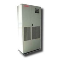
DEHUMIDIFICATION PHASE
During the dehumidication phase all DX units [optional] operate
with a reduced heat exchanger surface in order to decrease the
evaporating temperature and as a consequence to increase the
latent percentage
[Fig. 3].
Tab.1 — Refrigerant circuit pipes diameter
Tab.2 — Standard copper pipes characteristics
50% Coil surface
100% Coil surface
Capacity
Tev à 50% Tev à 100%
Diameter Thickness Minimum
bending
System
design
PED Category Max Copper
ss
Real copper
s
Safety ratio
Cooling Capacity
Refrigerant type
HP Gas line (0 / 10 m)
Liquid line (0 / 10 m)
HP Gas line (10 / 20 m)
Liquid line (10 / 20 m)
 Loading...