Page 56
TABLE 22
LCH152U
Outdoor Coil
Entering Air
Temp
Discharge +10
psig
Suction +5 psig
655 F 266 129
755 F 305 132
855 F 346 134
955 F 391 138
1055 F 443 141
1155 F 498 143
F-Charge Verification - Approach Method - AHRI Testing
(Fin/Tube Coil Continued)
1 Using the same thermometer, compare liquid tempera
ture to outdoor ambient temperature.
Approach Temperature = Liquid temperature (at con
denser outlet) minus ambient temperature.
2 Approach temperature should match values in table
23. An approach temperature greater than value
shown indicates an undercharge. An approach tem
perature less than value shown indicates an over
charge.
3 The approach method is not valid for grossly over or
undercharged systems. Use tables20 through22 as a
guide for typical operating pressures.
TABLE 23
APPROACH TEMPERATURE - 094, 122, 152
Unit
Liquid Temp. Minus Ambient Temp.
Full Load (Both Compressors)
094 5°F + 1 (2.8°C + 0.5)
122, 152 4°F + 1 (2.2°C + 0.5)
IV-STARTUP - OPERATION
Refer to startup directions and to the unit wiring diagram
when servicing. See unit nameplate for minimum circuit
ampacity and maximum fuse size.
A-Preliminary and Seasonal Checks
1 Make sure the unit is installed in accordance with the
installation instructions and applicable codes.
2 Inspect all electrical wiring, both field and factory installed
for loose connections. Tighten as required. Refer to unit di
agram located on inside of unit control box cover.
3 Check to ensure that refrigerant lines are in good
condition and do not rub against the cabinet or other
refrigerant lines.
4 Check voltage. Voltage must be within the range listed
on the nameplate. If not, consult power company and
have the voltage corrected before starting the unit.
5 Recheck voltage and amp draw with unit running. If
voltage is not within range listed on unit nameplate,
stop unit and consult power company. Refer to unit
nameplate for maximum rated load amps.
6 Inspect and adjust blower belt (see section on Blower
Compartment - Blower Belt Adjustment).
B-Cooling Startup See figures 22, 23 or 24
for circuits
NOTE-Crankcase heaters must be energized 24 hours be
fore attempting to start compressor. Set thermostat so that
there is no demand to prevent compressor from cycling.
Apply power to unit.
LCH092H, 102H, 120H and 150S, 150H (Figure 22 or 23)
1 Initiate first and second stage cooling demands ac
cording to instructions provided with thermostat.
2 First-stage thermostat demand will energize compres
sor 1 and condenser fans 1 and 2. Second-stage ther
mostat demand will energize compressor 2.
3 Units contain two refrigerant circuits or stages.
4 Each refrigerant circuit is separately charged with re
frigerant. See unit rating plate for correct amount of
charge.
LCH094U, 122U and 152U (Figure 24)
1 Initiate first and second stage cooling demands ac
cording to instructions provided with thermostat.
2 First-stage thermostat demand will energize compres
sor 1 and condenser fans 1, 2 and 3 on low speed..
Second-stage thermostat demand will energize com
pressor 2 and condenser fans 1, 2 and 3 on high speed.
3 Units contain one common (tandem) refrigerant circuit.
4 Refrigerant circuit is charged with refrigerant. See unit
rating plate for correct amount of charge.
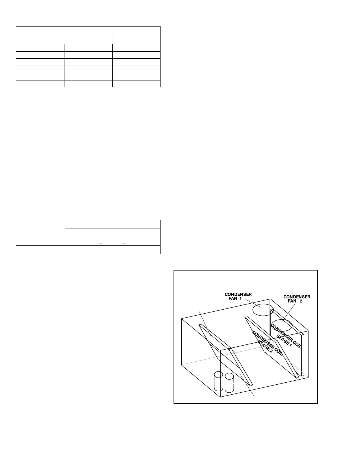
FIGURE 22
REFRIGERANT CIRCUITS -
Fin/Tube Coil
1
2
(BOTH FANS ARE ENERGIZED
WITH A Y1 DEMAND)
EVAPORATOR
COIL STAGE 1
EVAPORATOR
COIL STAGE 2
 Loading...


