Page 62
LGH/LCH036, 048, 060, 072, 074
9- While a W1 demand is present, 2
nd
-stage will operate
indefinitely.
10- Once a W2 demand is applied with 2
nd
-stage active,
power is supplied to the A3 ignition control.
11- After a 30-second pre-purge, the A3 spark ignitor
energizes and gas valve 1 (GV1) solenoid opens.
12- Both 1
st
- and 2
nd
-stage active at the same time
represents 3
rd
-stage. Timing circuits enable
3
rd
-stage, low fire, for approximately 10 minutes.
13- At the conclusion of the 10-minute time delay, timing
circuits activate the CAB high speed and high fire for
both gas valves; 4
th
-stage is energized.
14- If, at any time, the W2 demand is reduced to a W1
demand, the cycle restarts at step 4. Since the first
two tubes are already firing, the pre-purge delay and
gas ignition are not applicable.
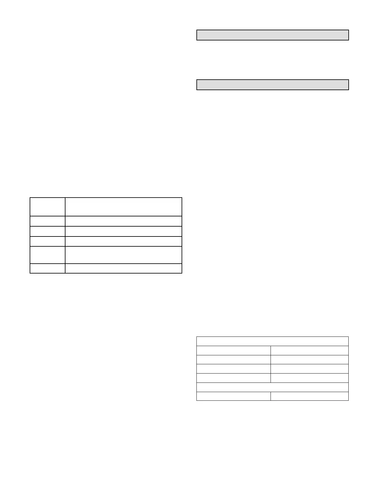
B-Ignition Control Diagnostic LEDs
TABLE 35
IGNITION CONTROL HEARTBEAT LED STATUS
LED
Flashes
Indicates
Steady Off No power or control hardware fault.
Steady On Power applied. Control OK.
3 Flashes Ignition lockout from too many trials.
4 Flashes
Ignition lockout from too many flame
losses within single call for heat.
5 Flashes Control hardware fault detected.
C-Limit Controls
Limit controls are factory-set and are not adjustable. On
single- and two-stage units, the primary limit is located to
the right of the combustion air inducer. See figure 36. On
four-stage units there are two primary limits; one is
located to the right of the combustion air inducer and the
other is located to the left of the combustion air inducer.
D-Heating Adjustment
Main burners are factory-set and do not require adjustment.
The following manifold pressures are listed on the gas valve.
Natural Gas Units - Low Fire - 2.0” w.c.
Natural Gas Units - High Fire - 3.5” w.c.
LP Gas Units - Low Fire - 5.9” w.c.
LP Gas Units - High Fire - 10.5” w.c.
Electric Heat Start-Up (LCH Units)
Optional electric heat will stage on and cycle with
thermostat demand. See electric heat wiring diagram on
unit for sequence of operation.
Advanced Air Flow Control Start-Up
High efficiency three-, four- and five-ton units equipped
with a direct drive blower and optional economizer allows
the installer to directly enter the design specified supply
air (blower) and outdoor air volume (economizer
minimum position) parameters without the need to
manually take measurements and adjust settings. The
system monitors supply air volume and outside air
volume and also has customizable diagnostics.
Note - Unit Controller configuration I.D. 1 character 7 is
factory-set to either S or L for the unit to operate in
Advanced Air Flow Control mode. When character 7 is set
to N or U, the Unit Controller will stage the indoor blower
speed but it won't control the damper minimum position.
The economizer is equipped with a PT5 pressure
transducer which provides feedback for damper
minimum position. See figure 27 for PT5 location. Refer to
the economizer installation instructions and Unit
Controller manual for additional economizer set-up.
Note - Modulation of dampers for free cooling does not
change.
ADesign Specifications
Use table 36 to fill in the field-provided,
design-specified supply air CFM and minimum required
outdoor/fresh air CFM.
TABLE 36
FIELD-PROVIDED DESIGN SPECIFICATIONS
Supply Air CFM
Heating CFM
Cooling High CFM
Cooling Low CFM
Ventilation CFM
Economizer Minimum Position
Outdoor Airflow CFM
 Loading...