GUIDE SPECIFICATIONS
T−Class Packaged Gas / Electric 7.5 to 12.5 tons / Page 11
1. Aluminized steel
2. Venturi to mix gas and air for proper combustion
3. Assembly to be removable as a single component
4. Individual burner removable from assembly
g. Limit Control:
1. Factory installed
2. Fixed temperature setting
3. Protect heating system from abnormal operating conditions
3. Solid state control board
a. Fan timer control
b. Diagnostic LED for trouble shooting
c. Continuous fan operation
4. Low voltage terminal strip
5. Supply fan:
a. Motor:
1. Direct drive
2. Permanently lubricated
b. Propeller type fan blade
6. [Optional Accessories]:
a. [Thermostat]
Specifier Note: Air Flow Nozzles are only available on the LF24 models 100, 115, 145, 175, 200, 230, 250, 300, 345, and 400.
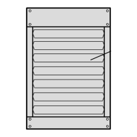
b.[Airflow Nozzles:]
1. [30° from horizontal]
2. [45° from horizontal]
3. [60° from horizontal]
4. [90° from horizontal]
Specifier Note: the High Altitude Pressure Switch Kit is only available on the LF24 models 100, 115, 145, and 175.
c. [High Altitude Pressure Switch Kit]
2.02 PRODUCT SUBSTITUTIONS
A. Substitutions: No substitutions permitted.
PART 3 EXECUTION
3.01 MANUFACTURER’S INSTRUCTIONS
Specifier Note: Article below is an addition to the CSI SectionFormat. Revise article below to suit project requirements and
specifier’s practice.
A. Compliance: Comply with manufacturer’s written data, including product technical bulletins, product catalog installation
instructions and product carton installation instructions.
3.02 EXAMINATION
A. Site Verification of Conditions: Verify substrate conditions, which have been previously installed under other sections, are
acceptable for product installation in accordance with manufacturer’s instructions.
3.03 INSTALLATION
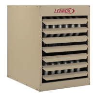
A. Install [Lennox LF24] gas fired unit heaters in accordance with manufacture’s instructions and regulations of authorities
having jurisdiction.
END OF SECTION
 Loading...