Page 19
OPERATION OF WHITE RODGERS 36H SERIES VALVE
(FIGURE 9) AND WHITE RODGERS 36G SERIES GAS
VALVE (FIGURE 10)
NOTE - STOP! Read the safety information at the begin-
ning of this section.
1 - Set thermostat to lowest setting.
2 - Turn o all electrical power to appliance.
3 - This appliance is equipped with an ignition device
which automatically lights burners. DO NOT attempt
to light the burners manually.
4 - Move lever to OFF.
5 - Wait ve minutes to clear out any gas. If you then
smell gas, STOP! Immediately call your gas supplier
from a neighbor’s phone. Follow the gas supplier’s
instructions. If you do not smell gas, go to next step.
6 - Move lever to ON.
7 - Turn on all electric power to unit.
8 - Set thermostat to desired setting.
9 - If appliance still will not operate, follow the instructions
“To Turn O Gas to Unit” and call your service
technician or gas supplier.
To Turn O Gas to Unit
1 - Set thermostat to lowest level.
2 - Turn o all electrical power to unit if service is to be
performed.
3 - Move lever to OFF
INLET
PRESSURE
PORT
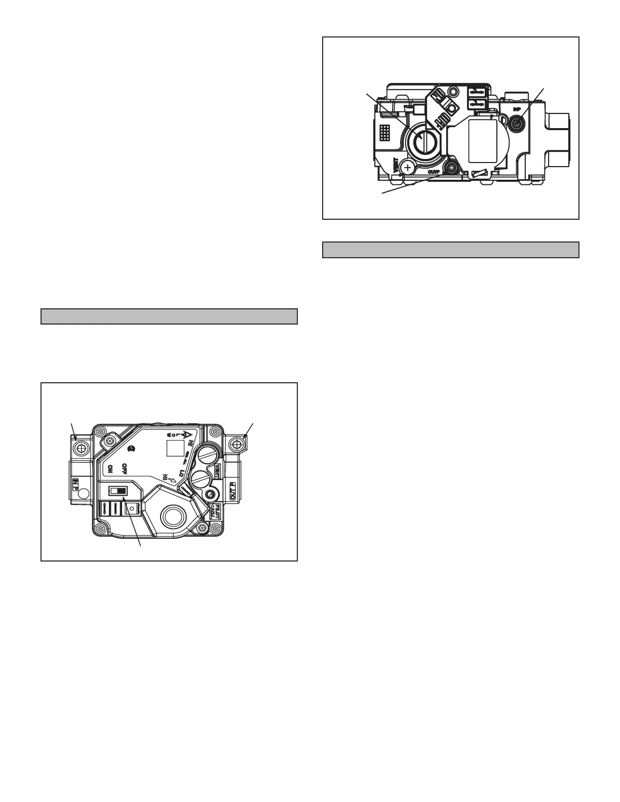
WHITE RODGERS 36H SERIES GAS VALVE
Two-Stage
GAS VALVE SWITCH SHOWN IN OFF POSITION
MANIFOLD
PRESSURE
OUTLET
MANIFOLD
PRESSURE
ADJUSTMENT
SCREW
FIGURE 9
WHITE RODGERS 36 GAS VALVE
Single-Stage
GAS VALVE SWITCH SHOWN IN OFF POSITION.
MANIFOLD
PRESSURE
ADJUSTMENT
SCREW
INLET
PRESSURE
PORT
MANIFOLD
PRESSURE
OUTLET
FIGURE 10
Heating Sequence of Operation
1 - When the thermostat calls for heat, the combustion
air inducer starts immediately.
2 - Combustion air pressure switch proves inducer
operation before allowing ignition sequence to
start. This switch is factory set and no adjustment is
necessary.
3 - After pre-purge of approximately 30 seconds, the
spark ignition is energized and the solenoid valves
open in the gas valve.
4 - The spark then ignites the gas, the ignition sensor
proves the ame and the combustion process
continues.
5 - In the event that the ame is not detected after the
rst 10-second trial for ignition, the controller will
repeat steps 3 and 4 an additional two times before
locking out the gas valve. Ignition control will then
automatically repeat steps 3, 4, and 5 after 60
minutes.
NOTE - To interrupt the 60-minute lockout period, move
thermostat from “Heat” to “OFF” then back to “Heat.” Heat-
ing sequence then restarts at step 1.
6 - The burners must light without noticeable crossover
delay. There must be no ame lifting from the burner
heads, ashback or burning within the burner. The
ames should be predominantly blue in color and
should be approximately centered in the tubes with
no apparent impingement taking place.
7 - The ignition control will energize the fan approximately
30 seconds after ignition is established.
8 - After the thermostat demand is satised the gas
valve is closed. Thirty seconds after the demand is
satised, the combustion air inducer is shut o.
9 - The ignition control will shut o the system fan
approximately 150 seconds after the gas valve is de-
energize.
 Loading...