Page 53
R410A Refrigerant
Units charged with R410A refrigerant operate at much
higher pressures than R22. The expansion valve and liquid
line drier provided with the unit are approved for use with
R410A. Do not replace them with components designed for
use with R22.
R410A refrigerant is stored in a pink cylinder.
IMPORTANT
Mineral oils are not compatible with R410A. If oil
must be added, it must be a polyol ester oil.
Manifold gauge sets used with systems charged with
R410A refrigerant must be capable of handling the higher
system operating pressures. The gauges should be rated
for use with pressures of 0−800 on the high side and a low
side of 30" vacuum to 250 psi with dampened speed to 500
psi. Gauge hoses must be rated for use at up to 800 psi of
pressure with a 4000 psi burst rating.
Turn off power to the unit.
C−Refrigerant Charge and Check
WARNING−Do not exceed nameplate charge under any
condition.
This unit is factory charged and should require no further
adjustment. If the system requires charge, reclaim the
charge, evacuate the system, and add required nameplate
charge.
NOTE − System charging is not recommended below 60_F
(15_C). In temperatures below 60_F (15_C) , the charge
must be weighed into the system.
If weighing facilities are not available, or to check the
charge, use the following procedure:
IMPORTANT − Charge unit in standard cooling mode.
1− Attach gauge manifolds and operate unit in cooling mode
until system stabilizes (approximately five minutes).
Make sure all outdoor air dampers are closed.
2− Check each system separately with all stages operat-
ing.
3− Use a thermometer to accurately measure the outdoor
ambient temperature.
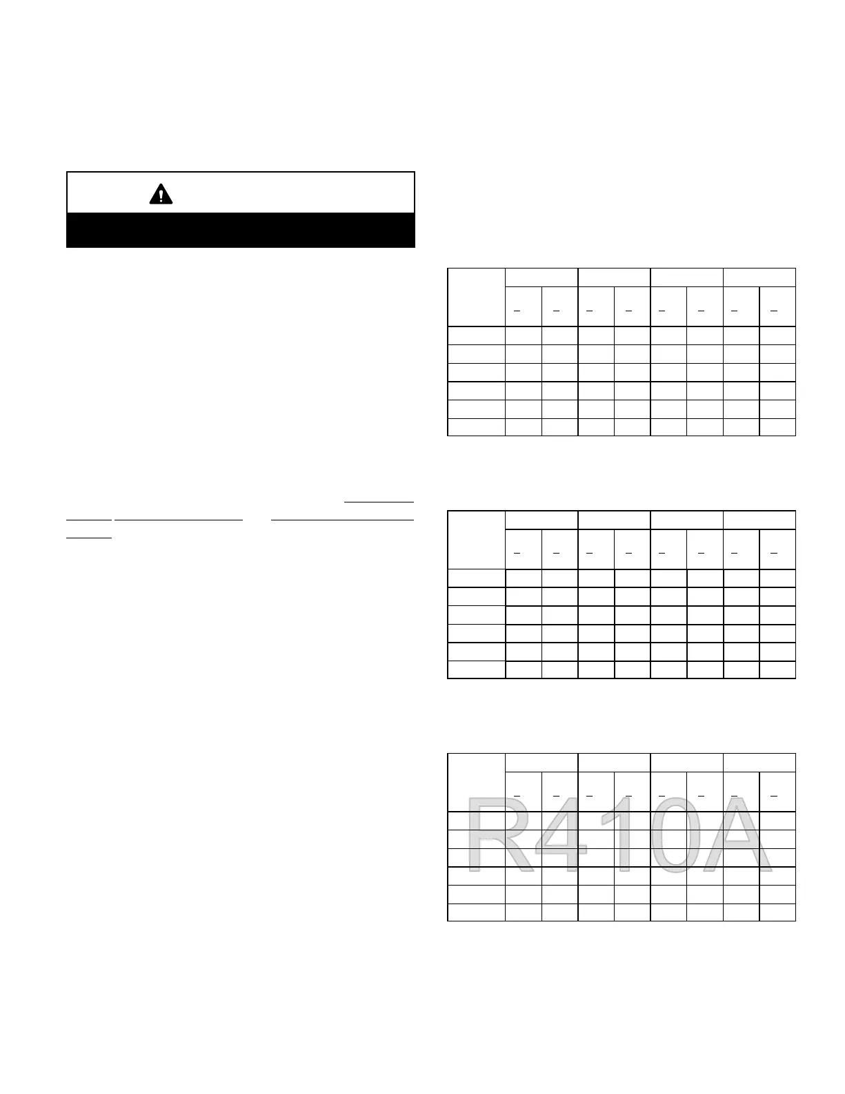
4− Apply the outdoor temperature to tables 6 through 19
to determine normal operating pressures.
5− Compare the normal operating pressures to the pres-
sures obtained from the gauges. Minor variations in
these pressures may be expected due to differences in
installations. Significant differences could mean that
the system is not properly charged or that a problem
exists with some component in the system. Correct
any system problems before proceeding.
6− If discharge pressure is high, remove refrigerant from
the system. If discharge pressure is low, add refriger-
ant to the system.
D Add or remove charge in increments.
D Allow the system to stabilize each time refriger-
ant is added or removed.
7− Use the following approach method along with the nor-
mal operating pressures to confirm readings.
TABLE 6
LGA/LCA Series 248 − R22 − CAV
Outdoor
Coil En-
tering Air
Temp
CIRCUIT 1 CIRCUIT 2 CIRCUIT 3 CIRCUIT 4
DIs
+
10
psig
Suc
+
5
psig
Dis
+
10
psig
Suc
+
5
psig
DIs
+
10
psig
Suc
+
5
psig
DIs
+
10
psig
Suc
+
5
psig
65_F* 158 68 156 72 157 75 156 72
75_F 181 69 183 77 190 82 190 80
85_F 207 70 211 77 218 83 217 80
95_F 235 71 241 78 248 84 248 82
105_F 269 74 273 80 282 86 284 86
115_F 304 76 310 82 320 87 322 85
*Outdoor fans may cycle on and off at this temperature.
TABLE 7
LGA/LCA Series 248 − R22 − VAV
Outdoor
Coil En-
tering Air
Temp
CIRCUIT 1 CIRCUIT 2 CIRCUIT 3 CIRCUIT 4
Dis.
+
10
psig
Suc.
+
5
psig
Dis.
+
10
psig
Suc.
+
5
psig
Dis.
+
10
psig
Suc.
+
5
psig
Dis.
+
10
psig
Suc.
+
5
psig
65_F* 150 71 150 75 158 79 156 81
75_F 181 73 180 77 190 81 190 82
85_F 212 75 210 79 220 82 220 83
95_F 242 78 241 80 252 83 254 84
105_F 274 80 272 82 285 84 288 86
115_F 306 82 302 84 315 85 320 87
*Outdoor fans may cycle on and off at this temperature.
TABLE 8
LGA/LCA Series 248 − R410A − CAV
Outdoor
Coil En-
tering Air
Temp
CIRCUIT 1 CIRCUIT 2 CIRCUIT 3 CIRCUIT 4
Dis.
+
10
psig
Suc.
+
5
psig
Dis.
+
10
psig
Suc.
+
5
psig
Dis.
+
10
psig
Suc.
+
5
psig
Dis.
+
10
psig
Suc.
+
5
psig
65_F* 248 120 250 134 250 139 251 136
75_F 284 122 287 137 288 143 290 139
85_F 324 125 329 139 329 145 332 142
95_F 367 127 374 141 375 147 379 145
105_F 415 131 425 144 425 150 430 147
115_F 468 139 478 146 475 152 485 150
*Outdoor fans may cycle on and off at this temperature.
 Loading...


