Page 45
ÉÉÉÉÉÉÉÉÉÉÉÉÉÉ
ÉÉÉÉÉÉÉÉÉÉÉÉÉÉ
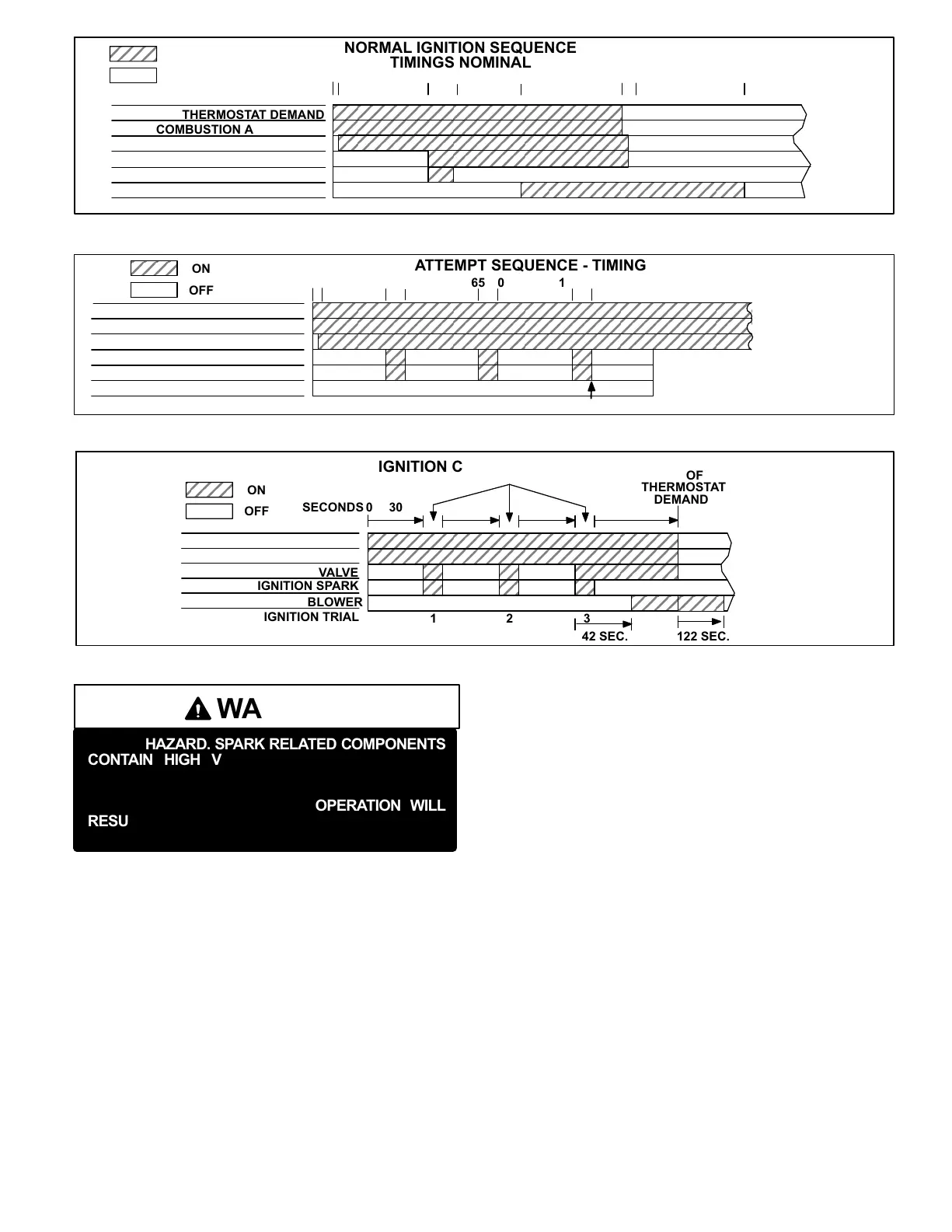
NORMAL IGNITION SEQUENCE
TIMINGS NOMINAL
THERMOSTAT DEMAND
COMBUSTION AIR BLOWER
GAS VALVE
IGNITION SPARK
BLOWER
IGNITION TRIAL
SECONDS 0 30 35 0 110
ON / CLOSED
OFF / OPEN
END OF
DEMAND
1
ÉÉÉÉÉÉÉÉÉÉÉÉÉ
ÉÉÉÉÉÉÉÉÉÉÉÉÉ
COMBUSTION AIR PROVE SWITCH
5 570
FIGURE 18
FIGURE 19
RETRIALS − IGNITION ATTEMPT SEQUENCE − TIMINGS NOMINAL
THERMOSTAT DEMAND
COMBUSTION AIR BLOWER
GAS VALVE
IGNITION SPARK
BLOWER
IGNITION TRIAL
SECONDS 0 30 35 70
ON
OFF
ÉÉÉÉÉÉÉÉÉÉÉÉÉÉÉÉÉÉÉ
ÉÉÉÉÉÉÉÉÉÉÉÉÉÉÉÉÉÉÉ
65 100 105
WATCHGUARD
LOCKOUT
COMBUSTION AIR PROVE SWITCH
ÉÉÉÉÉÉÉÉÉÉÉÉÉÉÉÉÉÉÉ
ÉÉÉÉÉÉÉÉÉÉÉÉÉÉÉÉÉÉÉ
5
FIGURE 20
ÉÉÉÉÉÉÉÉÉÉÉÉÉÉ
ÉÉÉÉÉÉÉÉÉÉÉÉÉÉ
THERMOSTAT DEMAND
COMBUSTION AIR BLOWER
GAS VALVE
IGNITION SPARK
BLOWER
IGNITION TRIAL
SECONDS 0 30
ON
OFF
IGNITION CONTROL TIMING
30
30
HEATING
CYCLE
6 (+3.4, −2.0) SEC.
END OF
THERMOSTAT
DEMAND
123
42 SEC. 122 SEC.
WARNING
SHOCK HAZARD. SPARK RELATED COMPONENTS
CONTAIN HIGH VOLTAGE WHICH CAN CAUSE
PERSONAL INJURY OR DEATH. DISCONNECT
POWER BEFORE SERVICING. CONTROL IS NOT
FIELD REPAIRABLE. UNSAFE OPERATION WILL
RESULT. IF THE CONTROL IS INOPERABLE, SIM-
PLY REPLACE THE ENTIRE CONTROL.
2−Heat Exchanger (Figures 15 and 16)
Two Styles used
The LGA/LGC units use aluminized steel inshot burners with
matching tubular aluminized steel (stainless steel is an option)
heat exchangers and two-stage redundant gas valves. LGA/
LGC uses two eleven tube/burners for high heat, two nine tube
burners for medium heat (if applicable, see unit nameplate)
and two six tube/burners for standard heat. Each burner uses
a burner venturi to mix gas and air for proper combustion.
Combustion takes place at each tube entrance. As hot com-
bustion gases are drawn upward through each tube by the
combustion air blower, exhaust gases are drawn out the top
and fresh air/gas mixture is drawn in at the bottom. Heat is
transferred to the air stream from all surfaces of the heat ex-
changer tubes. The supply air blowers, controlled by the main
control panel A55, force air across all surfaces of the tubes to
extract the heat of combustion. The shape of the tubes ensur-
es maximum heat exchange.
The gas valves accomplish staging by allowing more or less
gas to the burners as called for by heating demand.
3−Burner Assembly (Figure 21)
The burners are controlled by the spark electrode, flame sens-
ing electrode, gas valve and combustion air blower. The spark
electrode, flame sensing electrode and gas valve are directly
controlled by ignition control. Ignition control and combustion
air induceris controlled by main control panel A55.
Burners
All units use inshot burners (see figures 21 and 22). Burn-
ers are factory set and do not require adjustment. A peep
hole with cover is furnished in the heating access
panel for flame viewing. Always operate the unit with
the access panel in place. Burners can be removed
individually for service. Burner maintenance and
service is detailed in the SERVICE CHECKS sec-
tions of this manual.
 Loading...