Page 46
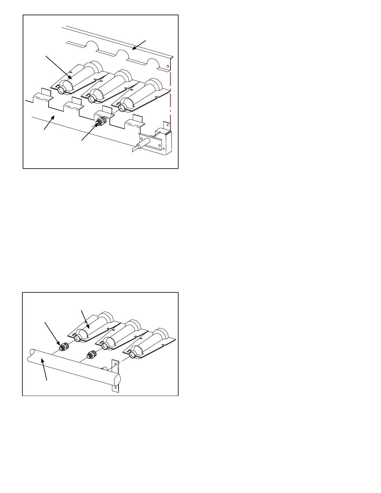
FIGURE 21
TYPICAL GAS BURNER ASSEMBLY
BURNERS
ORIFICE
BURNER
SUPPORT
BURNER
SUPPORT
CAP
Orifice
Each burner uses an orifice which is precisely matched to
the burner input. The orifice is threaded into the burner
manifold. The burner is supported by the orifice and will
easily slide off for service.
NOTE−Do not use thread sealing compound on the ori-
fices. Using thread sealing compound may plug the ori-
fices.
Each orifice and burner are sized specifically to the unit.
Refer to Lennox Repair Parts Listing for correct sizing in-
formation.
FIGURE 22
TYPICAL GAS MANIFOLD ASSEMBLY
BURNERS
MANIFOLD
ORIFICE
NOTE−In primary and secondary high temperature limits
S10, S99, S21, and S100 the ignition circuits in both gas
heat sections one and two are immediately de−energized
when terminals 1−3 open and the indoor blower mo-
tor is immediately energized when terminals 1−2
close. This is the primary and secondary safety shut−
down function of the unit.
4−Primary High Temperature Limits
S10 & S99
Figure 23 shows locations for temperature limits S10 and S99
on LGA/LCA models built up to production July 2004. S10 is
the primary high temperature limit for gas heat section one,
while S99 is the primary high temperature limit for gas heat
section two. S10 is located in the blower compartment and is
mounted on the end of the blower support panel which divides
the blower compartment from the heating compartment.
S99 is located on the blower support panel which separates
the second gas heat section from the outdoor condenser
section. S99 is accessed through a patch plate on the
condenser divider wall.
Figure 24 shows the location of production models August
2004 and later. S10 and S99 are located on the drip shield
behind the blower housing. In this location S10 and S99
serve as both primary and secondary limit.
Primary limit S10 is wired to the main control panel A55
which energizes burner 1 control (A3), while primary limit S99
is wired to the gas 2 panel A58 which energizes burner 2
control (A12). Its N.C. contacts open to de−energize the
ignition control when excessive temperature is reached in the
blower compartment. At the same time, the N.O. contacts of
S10 and S99 close energizing the blower relay coil K3 through
control A55. If either limit trips the blower will be energized.
Three limits with different actuating temperatures are
used for limits S10 and S99 (standard and high first heat
section use two different limits, while yet another limit is
used for the second heat section). All three limits are
SPDT N.C. auto−reset limits.
Limit set point are factory set and cannot be adjusted. If limit
must be repalced, same type and set point must be used. See
Lennox Repair Parts Handbook.
5−Secondary High Temperature Limits
S21 & S100 (Production to July 2004)
S21 is the secondary high temperature limit for heat sec-
tion one, while S100 is the secondary high temperature
limit for heat section two. Like the primary limits, the sec-
ondary limits are located in the blower compartment.
S21 and S100 are mounted on a horizontal panel lo-
cated behind the blowers (see figure 23).
Secondary limit S21 is also wired to the main control
panel A55, while secondary limit S100 is wired to the gas
2 panel A58. The secondary limits function in the same
manner as the primary limits, but are factory set to actu-
ate at different temperatures. The N.O. contacts of both
S21 and S100 are connected to the blower relay coil K3
through control A55. If either limit trips the blower will be
energized. All limits used are SPDT N.C. auto−reset lim-
its.
LGA/LGC units date coded August 2004 or later will not
be equipped with secondary limts S21 and S100.
Limit set point are factory set and cannot be adjusted. If limit
must be repalced, same type and set point must be used. See
Lennox Repair Parts Handbook.
 Loading...