Page 47
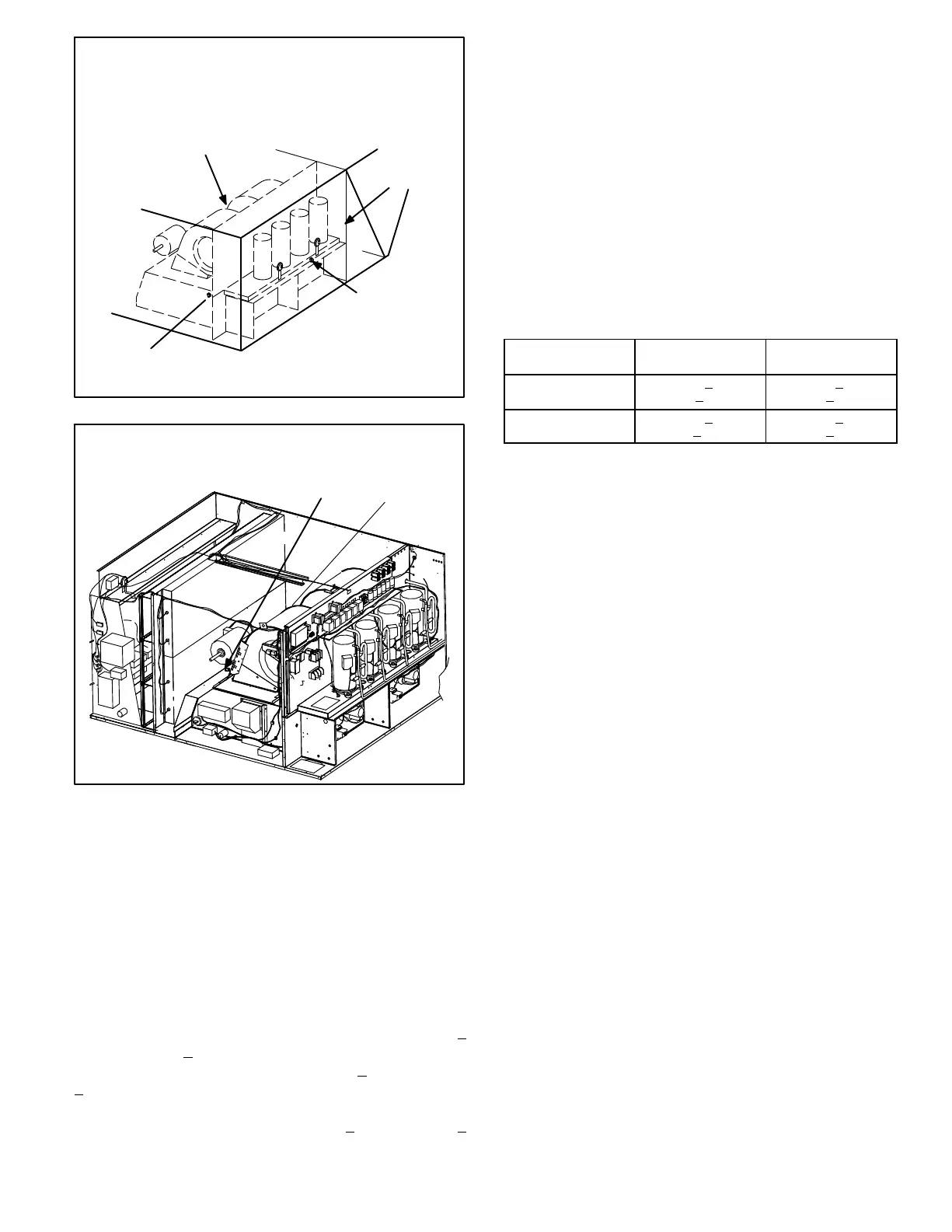
LGA/LGC HEATING COMPONENTS
(Production to July 2004)
FIGURE 23
PRIMARY HIGH
TEMP. LIMIT S99
(SECOND HEAT SECTION)
access patch plate is located
on condenser divider panel
PRIMARY HIGH
TEMP. LIMIT S10
(FIRST HEAT SECTION)
SECONDARY HIGH TEMP. LIMIT S21
FIRST HEAT SECTION and S100
(SECOND HEAT SECTION
HIDDEN BEHIND BLOWERS)
CONDENSER
DIVIDER PANEL
LGA/LGC HEATING COMPONENTS
(Production August 2004 and Later)
FIGURE 24
S10
S99
6−Flame Rollout Limits S47 and S69
Flame rollout limits S47 (first heat section) and S69 (sec-
ond heat section) are SPST N.C. high temperature limits lo-
cated just above the burner air intake opening in the burner en-
closures (see figure 16). S47 is wired to the main control panel
A55, while S69 is wired to the gas 2 panel A58. When S47 or
S69 senses flame rollout (indicating a blockage in the
combustion air passages), the corresponding flame rol-
lout limit trips, and the ignition control immediately
closes the gas valve.
For all units production to July 2004, limit S47 and S69 in
standard heat units are factory preset to open at 250_F +
12_F (121.1_C + 6.7_C) on a temperature rise, while on
high heat units both limits open at 270_F +
12_F (132.2_C
+
6.7_C) on a temperature rise. All flame rollout limits are-
manual reset. Production units August 2004; limit set point for
both standard heat and high heat is 290_F +
12_F (143.3_C +
6.7_C) .
7−Combustion Air Prove Switches S18 & S45
Prove switches S18 (first heat section) and S45 (second heat
section) are located in the compressor compartment. Switches
are identical, SPST N.O. and monitor combustion air inducer
operation. Switch S18 is wired to the main control panel A55,
while S45 is wired to the gas 2 panel A58. The switches
close on a negative pressure fall, allowing power to the igni-
tion controls. The switches open on a on a pressure rise
(less negative pressure). The combustion air prove
switches are factory set and not adjustable. Table 3 shows
prove switch settings for unit production dates before and
after February 2009.
TABLE 3
S18 & S45 Prove Switch Settings
Unit Production
Date
Close wc
(Pa)
Open wc
(Pa)
Feb 2009 & Later
0.25 + 5
(62.3+
12.4)
0.10+5
(24.8+
12.4)
Prior to Feb 2009
0.46+5
(114+12.4)
0.31+5
(77.2+12.4)
8−Combustion Air Inducers B6 and B15
Combustion air inducers B6 (first heat section) and B15 (sec-
ond heat section) are identical inducers which provide fresh air
to the corresponding burners while clearing the combustion
chamber of exhaust gases. The inducers begin operating
immediately upon receiving a thermostat demand and are
de−energized immediately when thermostat demand is sat-
isfied.
460V units date coded 10−2003 and after use a 460V inducer
motor and all other inducers use a 208/230V single-phase
PSC motor and a 4.81in. x 1.25in. (122mm x 32mm) blower
wheel. All motors operate at 3200RPM and are equipped with
auto-reset overload protection. Inducers are supplied by vari-
ous manufacturers. Ratings may vary by manufacturer. Spe-
cific inducer electrical ratings can be found on the unit rating
plate.
All combustion air inducer motors are sealed and can-
not be oiled. The inducer cannot be adjusted but can be
disassembled for cleaning.
9−Combustion Air Motor Capacitors C3 & C11
The combustion air inducer motors in all LGA/LGC units
require run capacitors. Capacitor C3 is connected to
combustion air inducer B6 and C11 is connected to com-
bustion air inducer B15. Both capacitors are rated at 3
MFD and 370VAC.
 Loading...