12/09 506217−01
*2P1209* *P506217-01*
Page 1
CONTROLS
KITS AND ACCESSORIES
Litho U.S.A.
E2009 Lennox Industries Inc.
Dallas, Texas, USA
506217−01
12/09
Supersedes 505080M
LonTalk
®
MODULE KIT
INSTALLATION INSTRUCTIONS FOR LONTALK MODULE KIT
(11W28) USED WITH LG/LC/LH & SG/SC AND ENERGENCET ROOFTOP UNITS
Table of Contents
Application 2. . . . . . . . . . . . . . . . . . . . . . . . . . . . . . . . . . .
Installation 2. . . . . . . . . . . . . . . . . . . . . . . . . . . . . . . . . . . .
Configuring IMC / M2 Unit Controller 4. . . . . . . . . . . .
Communications Check Out 5. . . . . . . . . . . . . . . . . . . .
LonWorks Network Connection 6. . . . . . . . . . . . . . . . . .
Network Cable 6. . . . . . . . . . . . . . . . . . . . . . . . . . . . . . .
Network Limits 6. . . . . . . . . . . . . . . . . . . . . . . . . . . . . . . .
Network Integration 7. . . . . . . . . . . . . . . . . . . . . . . . . . . .
Data Update Rate 7. . . . . . . . . . . . . . . . . . . . . . . . . . . . .
Start Up & Normal Unit Operation 7. . . . . . . . . . . . . .
Zone Sensor Setpoints 7. . . . . . . . . . . . . . . . . . . . . . . . .
Inputs to/Outputs from IMC / M2 Unit Controller 8. . .
Alarm Codes 8. . . . . . . . . . . . . . . . . . . . . . . . . . . . . . . .
NOTE − Disregard shipping and packing list and installation
sections when module is factory−installed.
Shipping and Packing List
Package 1 of 1 contains:
1− LonTalk module
4− #6 − 32 X 7/8" Screws
1− Mounting plate (used on 090−300S units only)
2− #10 − 16 X 5/8" Sheet metal screws (used on
090−300S units only)
1− 3−ft. length SYSBUS cable
1− 3 ft. length thermostat wire
1− Wiring diagram
Technical Assistance
For assistance contact Lennox Technical Support at
800−453−6669.
Version Required
This module requires a rooftop unit IMC M1−7 (version 5.02
or higher), M1−8, or M2 Unit Controller. An IMC upgrade kit
is available for earlier M1−7 versions. M1−6 and earlier IMC
versions cannot be upgraded for use with the LonTalk
module. M1−8 displays version when powered up in the
scrolling text (may need to clear error codes). For display-
ing version on M1−7:
1. Locate IMC board in compressor area. Refer to IMC
manual provided with rooftop unit.
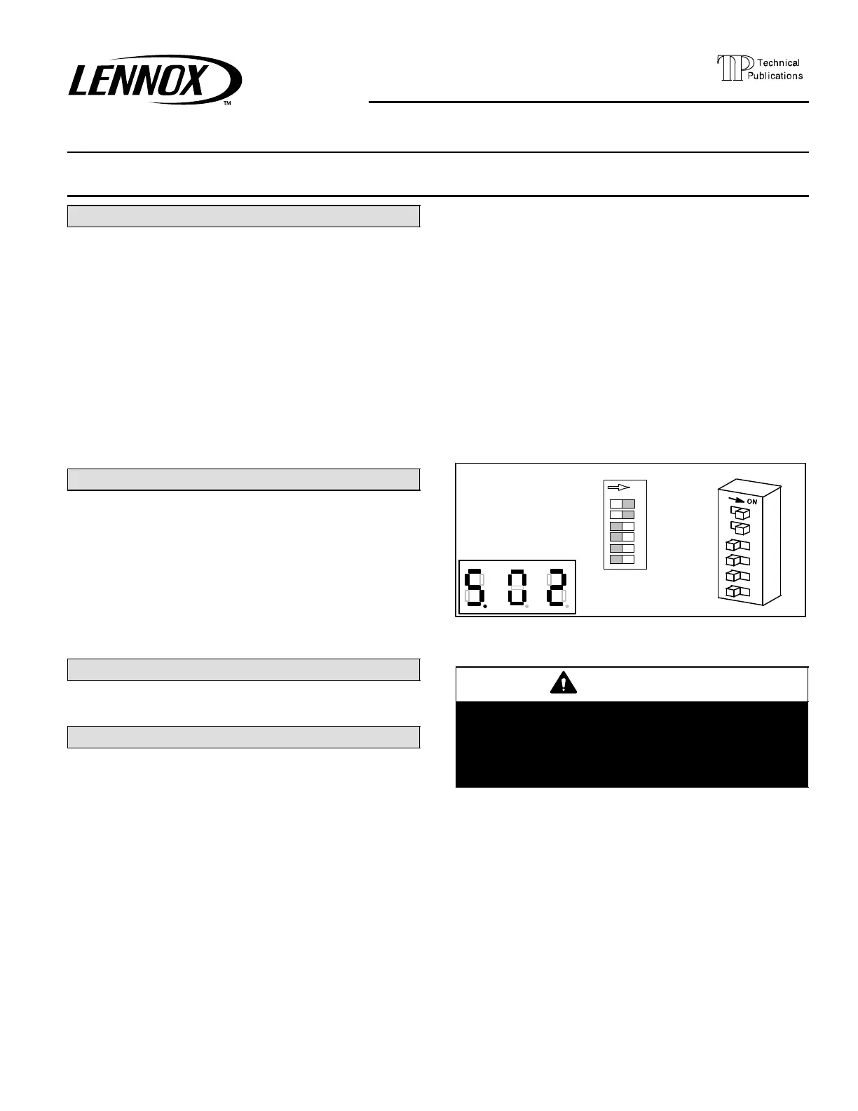
2. Set the MODE DIP UNIT TEST" and RECALL"
switches to ON" (see figure 2).
3. The IMC LEDs will display the current IMC version
(see figure 1).
4. Be certain to return the UNIT TEST" and RECALL"
switches to OFF" after viewing the version number.
Communication to the IMC is interrupted while these
MODE DIP switches are ON".
ON
UNIT TEST
RECALL
ECTO
TEMP
OPT2
SHIFT
MODE
Set the MODE DIP
UNIT TEST" and RE-
CALL" switches to ON".
LED will display cur-
rent software version.
Figure 1. Check M1−7, M1−8 Software Version
and Address
WARNING
Improper installation, adjustment, alteration, ser-
vice or maintenance can cause property damage,
personal injury or loss of life. Installation and ser-
vice must be performed by a qualified installer or
service agency.
 Loading...
