Do you have a question about the Lennox LGH150H and is the answer not in the manual?
| Cooling Capacity | 144, 000 BTU |
|---|---|
| Refrigerant Type | R-410A |
| Phase | 3 |
| Compressor Type | Scroll |
| Weight | 920 lbs |
| Stages | Single |
| Sound Level | 78 dBA |
Details the contents of Package 1 and instructions for checking shipping damage.
Provides general guidance and supersedes local codes, emphasizing consultation with authorities.
Provides essential safety warnings regarding electrical shock, explosion, and proper handling of equipment.
Specifies required clearances around the unit for installation and service based on unit type.
Guidelines for installing the unit on non-combustible surfaces or approved roof frames for downflow discharge.
Important notices regarding refrigerant venting, construction site usage, and potential unit damage.
Guidance on connecting exterior ducts, joints, and openings, including insulation and weatherproofing.
Instructions for safely rigging the unit for lifting, including detaching base protection and using proper lifting points.
Details on making condensate drain connections, including trap installation and venting requirements.
Instructions for modifying the unit for bottom drain connection, including drilling and reassembly steps.
Guidance on connecting gas supply piping, considering local codes, pressure drops, and drip leg installation.
Procedure for pressure testing gas lines, emphasizing caution to avoid damaging the gas valve.
Procedure for applying high altitude derate adjustments using a conversion sticker and referring to altitude adjustment tables.
Details on routing field wiring, connecting power supplies, and specific wiring instructions for 208V units.
Guidance for units with optional inverters operating on unbalanced three-phase power, including up-sizing.
Recommendations for locating the room thermostat to ensure accurate temperature readings.
Instructions for routing and connecting thermostat wiring to the Unit Controller for proper operation.
Information on operating the unit using a room sensor for temperature control, including wiring details.
Wiring instructions for humidity sensors or dehumidification inputs on hot gas reheat units.
Details on operating the blower, including startup procedures, continuous vs. auto modes, and safety checks.
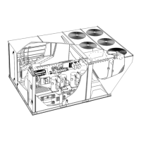
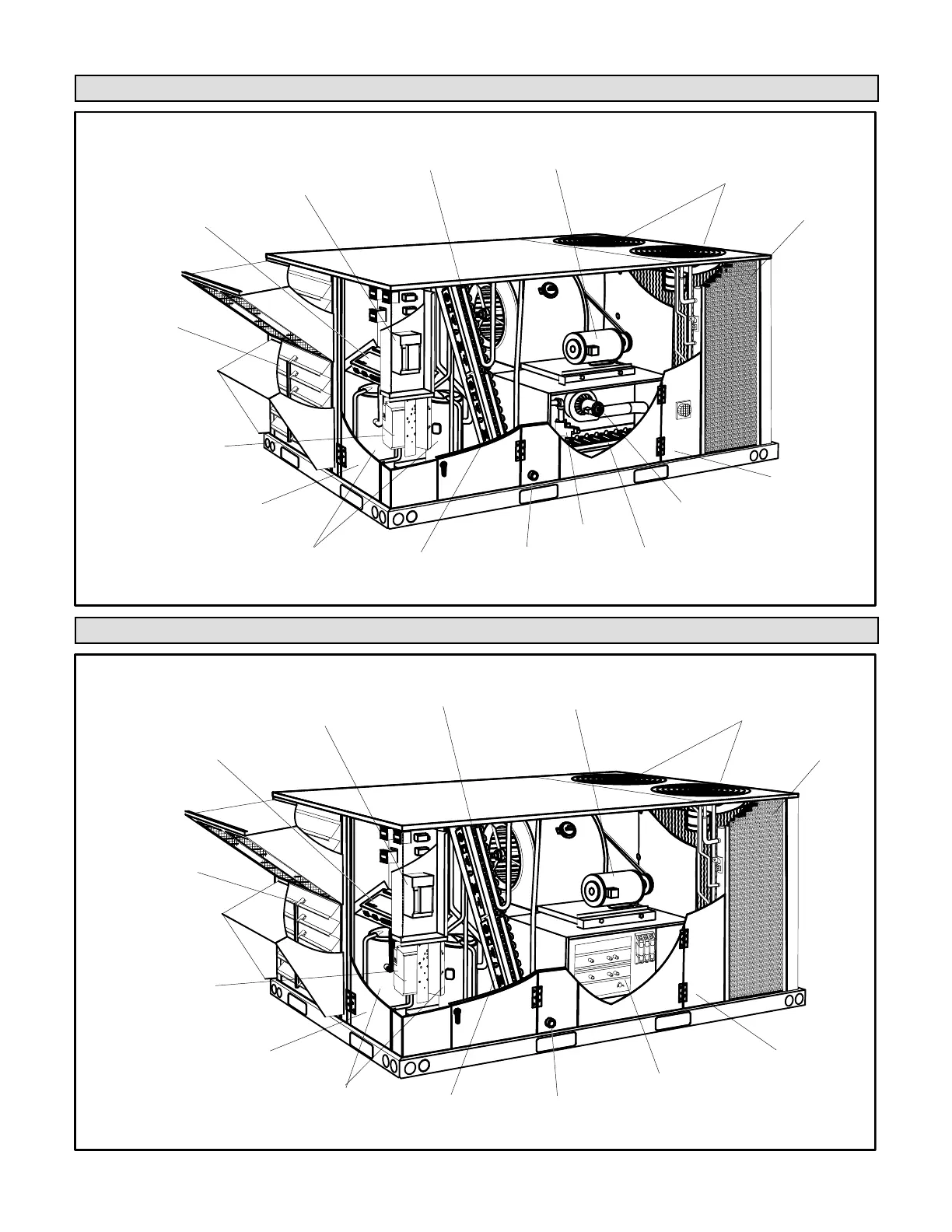
Procedure for accessing the blower assembly by sliding the frame out of the unit for service.
Methods for determining unit CFM using blower tables, static pressure, and RPM readings.
Instructions for adjusting pulley alignment and belt tension for belts without a tensioner.
Procedure for checking belt tension by measuring span length and deflection force to prevent overtensioning.
Specifications for factory-installed belt drive kits, including motor HP, drive kit number, and RPM range.
Data on power exhaust fan performance, correlating static pressure with air volume exhausted.
Tables detailing air resistance values for various factory and field-installed options and accessories.
Tables listing manufacturer's numbers for drive components, with and without tensioners.
Instructions for initiating cooling start-up, including crankcase heater energization and thermostat settings.
Details on R410A refrigerant, including operating pressures, gauge requirements, and oil compatibility.
Diagrams illustrating refrigerant flow for different coil types and fan configurations.
Procedure for checking refrigerant charge using pressures and temperature, with specific examples.
Procedure for verifying refrigerant charge for Fin/Tube coils, using operating pressures and approach method.
Details on high pressure, low pressure, freezestat, and thermal protector switches for compressor safety.
Explanation of how outdoor temperature affects condenser fan operation for units with two or three fans.
Critical safety warnings regarding electrical shock, explosion, smoke potential, and manual ignition prohibition.
Steps for placing the unit into operation, including gas valve checks and igniter system.
Describes the sequence of events for gas heating, including inducer, ignition, and flame proving.
Information on factory-set limit controls and gas manifold pressures for heating adjustment.
Procedure for starting up electric heat options, including SCR controller setup and operation.
Guidance on entering design CFM values into the Unit Controller for various operating modes.
Setting minimum damper positions for ventilation air volumes in occupied modes based on blower CFM.
Configuration options for bypassing the VFD manually or automatically for constant air volume mode.
Summary of cooling operation for inverter and direct drive blowers, including thermostat stage control.
Procedure for setting blower speed, CFM, and damper minimum positions for direct drive units.
Explanation of how hot gas reheat provides dehumidification by routing hot gas to a reheat coil.
Diagrams illustrating refrigerant flow for both reheat mode and standard cooling mode.
Details on the L14 reheat coil solenoid valve operation and adjusting the reheat setpoint.
Guidance on annual unit inspection, filter checking, replacement, and lubrication requirements.
Procedure for examining, cleaning, and checking the ignitor gap for gas burners.
Instructions for cleaning the combustion air inducer wheel and inlet louvers for optimal operation.
Information on gas heat exchanger inserts and procedures for cleaning evaporator and condenser coils.
Guidance on annually inspecting the supply air blower wheel for accumulated dirt or dust.
Instructions for setting up BACnet module integration, including MAC address and parameter configurations.
Configuration steps for room sensor, CPC/LSE gateway settings, and network addresses.
Table of target settings for BACnet modules, covering compressor run time, reheat setpoint, and DCV parameters.
Details on configuring ID 1 for Humiditrol, Economizer, Power Exhaust, and Air Flow Control options.
Details on configuring ID 2 for Air Flow Proving, Dirty Filter Switch, Load Shedding, and Phase Detection.
Sections for recording inspection results, voltage checks, and factory/field installed accessories verification.
Fields for recording compressor rotation, amps, volts, ambient temp, pressures, and fan amps.
Sections for electric and gas heating checks, including limits operate, manifold pressure, and fuel type.
Checks for blower pulley alignment, belt tension, and accessory operations like economizer and power exhaust.