
Do you have a question about the Lennox LRP14G and is the answer not in the manual?
| Type | Heat Pump |
|---|---|
| SEER Rating | 14 |
| HSPF Rating | 8.2 |
| Compressor Type | Scroll |
| Refrigerant | R-410A |
| Stages | Single-stage |
| Voltage | 208/230V |
| Cooling Capacity (BTU/h) | 24, 000 - 60, 000 |
| Warranty | 10-Year Limited Warranty on Compressor and 5-Year Limited Warranty on Parts |
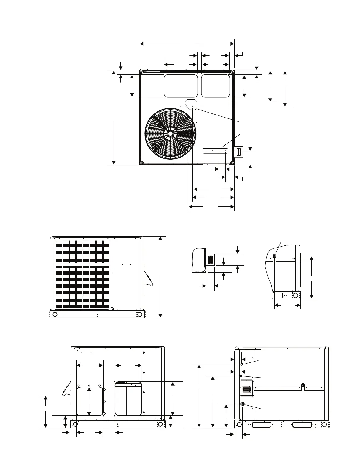
Detailed physical dimensions for the small base gas/electric unit.
Detailed physical dimensions for the large base gas/electric unit.
Specifications for roof curb openings for the small base unit.
Specifications for roof curb openings for the large base unit.
Dimensions for adjustable pitch roof curb installations.
Procedures for unit inspection and selecting installation site.
Conditions for using unit during construction to avoid warranty void.
Minimum clearances and unit rigging instructions for safe installation.
Guidelines for venting combustion products.
Instructions for attaching the vent hood to the unit.
Requirements for designing and installing ductwork.
Information on air filter installation and maintenance.
Proper installation and trapping of the condensate drain line.
Recommendations and safety for gas piping installation.
Requirements for electrical power supply and wiring connections.
Room thermostat location and wiring recommendations.
Steps and checks for initiating the heating function.
Post-start checks, pressure adjustments, and burner setup.
Proper setting for heat anticipator to control heating cycles.
Sequence of operation for the cooling system.
Values and checks for optimal cooling system performance.
Heating sequence, blower delays, and critical safety controls.
Routine tasks like filter changes and coil cleaning.
Lubrication, cleaning, and protection of motors and coils.
Instructions for cleaning burners, vent outlet, and heat exchanger.
Understanding LED status for troubleshooting control system faults.
Installation and function of optional heater accessories.
Operation sequence for the cooling mode in heat pumps.
Operation sequences for heat pump and auxiliary electric heat.
How the defrost system operates to prevent ice buildup.
Timing, pressure switches, and diagnostic LEDs for defrost control.
Performance values for AC units based on air temperature.
Performance values for HP units in cooling mode.
Performance values for HP units in heating mode.


