Page 23
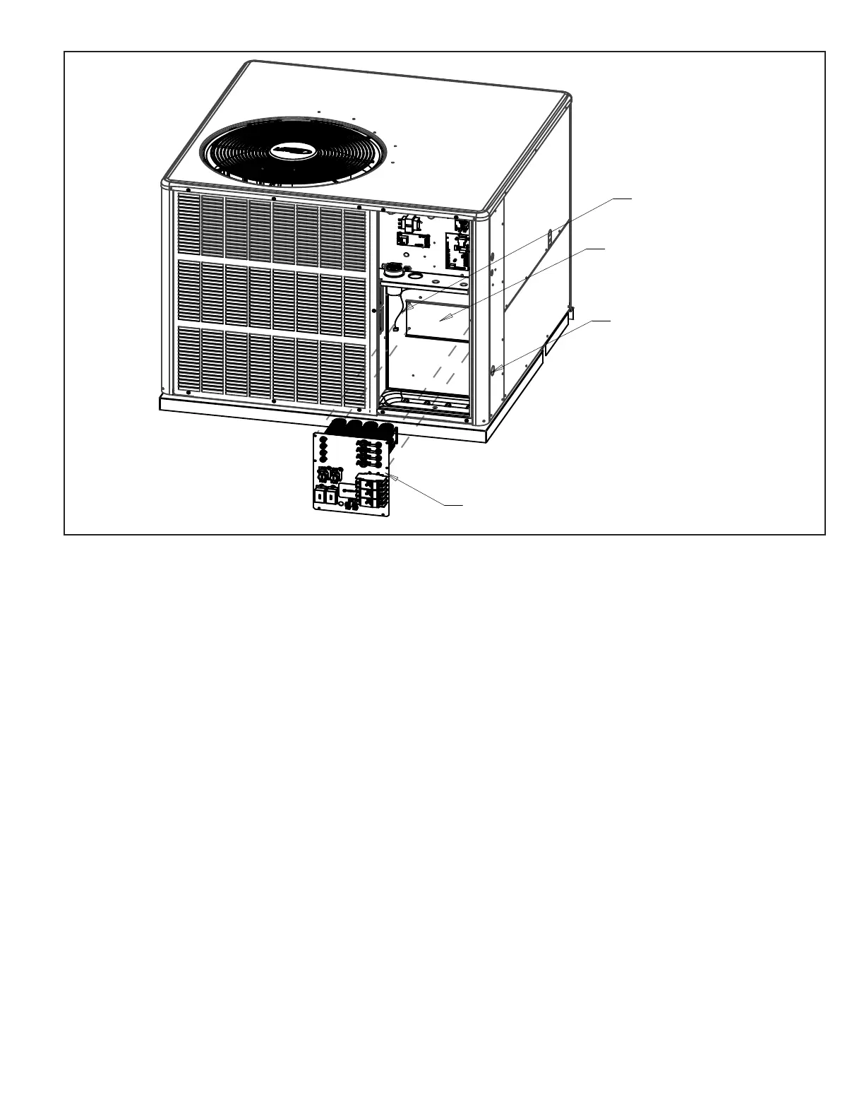
Figure 11.
Heater Kit Accessory (if used)
The unit is fully equipped for operation without auxiliary
heat. A heater kit accessory may also be used. To install
the heater kit accessory (see Figure 11):
1. Disconnect the power and open the main control
access.
2. Disconnect the plug separating the high voltage wire
harness. Remove the high voltage wire harness plug
and discard.
3. Remove the heater blocko by removing the four
screws holding it in place.
4. Insert the heater into the control panel and fasten in
the same mounting holes.
5. Plug the heater wiring harness into the wire harness
on the control assembly. Field wiring of the auxiliary
heater is separate from the unit power supply. Wire the
power supply wiring for the heater to the appropriate
connections on the heater kit.
Sequence of Operation
Blower Control
Units are equipped with a variable speed motor that is capable
of maintaining a specied CFM throughout the external
static range. A particular CFM can be obtained by positioning
jumpers (COOL, HEAT, and ADJUST) on the blower control.
The HEAT and COOL jumpers are labeled A, B, C and D.
Each of the numbers corresponds with an air volume
(CFM) setting. The ADJUST jumper is labeled Test, -,
+, and Norm. The + and - pin settings are used to add
or subtract a percentage of the CFM selected. The Test
jumper is used to operate the motor in the test mode.
Figure 12 shows the blower control.
The CFM LED located on the blower control ashes one
time per 100 cfm to indicate selected blower speed. For
example, if the unit is operating at 1200 CFM, the CFM
LED will ash 12 times. If the CFM is 1150, the CFM
LED will ash 11 full times plus one fast or half ash. At
times, the light may appear to icker or glow. This takes
place when the control is communicating with the motor
between cycles. This is normal operation. Read through
the jumper settings section before adjusting the jumper to
obtain the appropriate blower speed. To change jumper
positions, gently pull the jumper o the pins and place it
on the desired set of pins. The following section outlines
the dierent jumper selections available and conditions
associated with each one. Refer to Figure 12.
From the engineering handbook and/or specication
sheet, determine which row most closely matches the
desired CFM. Once a specic row has been chosen (+,
NORMAL, or -), CFM volumes from other rows cannot be
used. Below are descriptions of the jumper selections.
The variable speed motor slowly ramps up to and down
from the selected air ow during both cooling and heating
 Loading...


