Page 43
4 − Move gas valve switch to OFF.
5 − Replace the upper access panel.
Failure To Operate
If the unit fails to operate, check the following:
1 − Is the thermostat calling for heat?
2 − Are access panels securely in place?
3 − Is the main disconnect switch closed?
4 − Is there a blown fuse or tripped breaker?
5 − Is the filter dirty or plugged? Dirty or plugged filters will
cause the limit control to shut the unit off.
6 − Is gas turned on at the meter?
7 − Is the manual main shut-off valve open?
8 − Is the internal manual shut-off valve open?
9 − Is the unit ignition system in lockout? If the unit locks out
again, inspect the unit for blockages.
Heating Sequence Of Operation
1 − When thermostat calls for heat, combustion air inducer
starts.
2 − Combustion air pressure switch proves blower opera-
tion. Switch is factory set and requires no adjustment.
3 − After a 15−second prepurge, the hot surface ignitor en-
ergizes.
4 − After a 20−second ignitor warm−up period, the gas
valve solenoid opens. A 4−second Trial for Ignition peri-
od begins."
5 − Gas is ignited, flame sensor proves the flame, and the
combustion process continues.
6 − If flame is not detected after first ignition trial, the igni-
tion control will repeat steps 3 and 4 four more times
before locking out the gas valve (WATCHGUARD"
flame failure mode). The ignition control will then auto-
matically repeat steps 1 through 6 after 60 minutes.
To interrupt the 60−minute WATCHGUARD" period,
move thermostat from Heat" to OFF" then back to
Heat". Heating sequence then restarts at step 1.
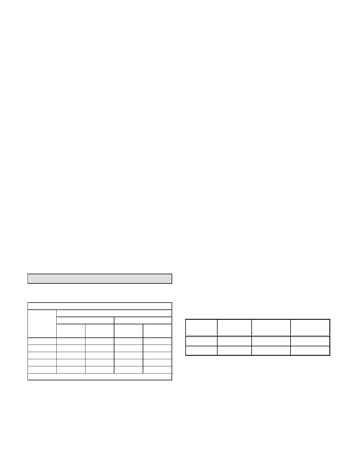
Gas Pressure Adjustment
Gas Flow (Approximate)
TABLE 11
GAS METER CLOCKING CHART
ML193
Unit
Seconds for One Revolution
Natural LP
1 cu ft
Dial
2 cu ft
Dial
1 cu ft
Dial
2 cu ft
DIAL
−045 80 160 200 400
−070 55 110 136 272
−090 41 82 102 204
−110 33 66 82 164
−135 27 54 68 136
Natural−1000 btu/cu ft LP−2500 btu/cu ft
Furnace should operate at least 5 minutes before check-
ing gas flow. Determine time in seconds for two revolu-
tions of gas through the meter. (Two revolutions assures a
more accurate time.) Divide by two and compare to time
in table 11 below. If manifold pressure matches table 12
and rate is incorrect, check gas orifices for proper size and
restriction. Remove temporary gas meter if installed.
NOTE − To obtain accurate reading, shut off all other gas
appliances connected to meter.
Supply Pressure Measurement
When testing supply gas pressure, use the 1/8" N.P.T.
plugged tap or pressure post located on the gas valve to
facilitate test gauge connection. See figure 67. Check gas
line pressure with unit firing at maximum rate. Low pres-
sure may result in erratic operation or underfire. High pres-
sure can result in permanent damage to gas valve or over-
fire.
On multiple unit installations, each unit should be checked
separately, with and without units operating. Supply pres-
sure must fall within range listed in table 12.
Manifold Pressure Measurement
1 − Remove the threaded plug from the outlet side of the
gas valve and install a field−provided barbed fitting.
Connect to a manometer to measure manifold pres-
sure.
2 − Start unit and allow 5 minutes for unit to reach steady
state.
3 − While waiting for the unit to stabilize, observe the
flame. Flame should be stable and should not lift from
burner. Natural gas should burn blue.
4 − After allowing unit to stabilize for 5 minutes, record
manifold pressure and compare to value given in table
12.
NOTE − Shut unit off and remove manometer as soon as an
accurate reading has been obtained. Take care to remove
barbed fitting and replace threaded plug.
TABLE 12
Supply Line and Manifold Pressure (inches w.c.)
Unit Fuel
Manifold
Pressure
Line Pressure
All Nat. Gas 3.5 4.5 − 10.5
All L.P. Gas 10.0 11.0 − 13.0
NOTE − A natural to L.P. propane gas changeover kit is nec-
essary to convert this unit. Refer to the changeover kit
installation instruction for the conversion procedure.
 Loading...