5
Operating the Gas Valve (Figure 2)
1 . STOP! Read the safety information at the beginning of
this section.
2. Set the thermostat to the lowest setting.
3. Turn off all electrical power to the unit.
4. This furnace is equipped with an ignition device which
automatically lights the burners. Do not try to light the
burners by hand.
5. Remove the upper access panel.
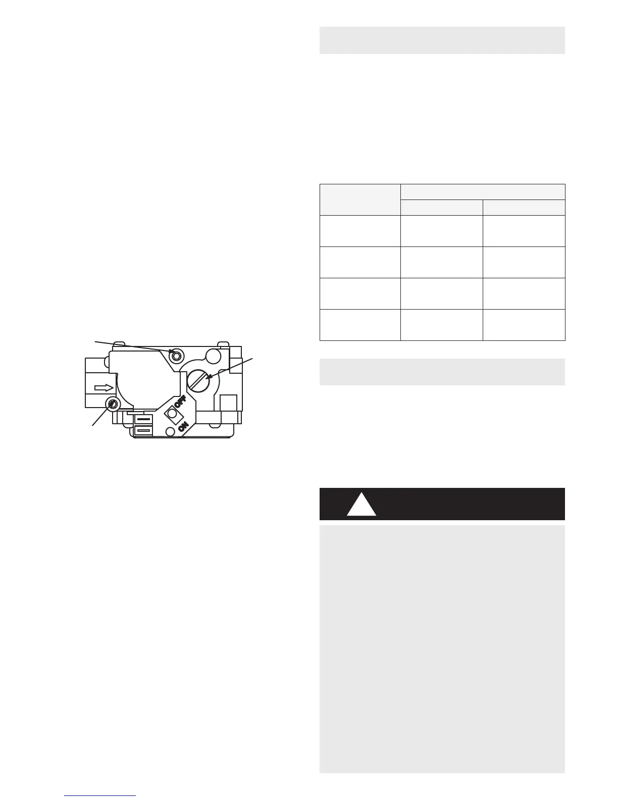
6. Move lever on gas valve to OFF. See gure 2.
7. Wait ve minutes to clear out any gas. If you then smell
gas, STOP! Immediately call your gas supplier from a
neighbour’s phone. Follow the gas supplier’s instructions.
If you do not smell gas go to next step.
8. Move lever on gas valve to ON. See gure 2.
Figure 2
GAS VALVE SHOWN IN OFF POSITION
MANIFOLD
PRESSURE
OUTLET
PORT
INLET
PRESSURE
PORT
MANIFOLD
PRESSURE
ADJUSTMENT
SCREW
White Rodgers 3600 Gas Valve
9. Replace the upper access panel.
10. Turn on all electrical power to to the unit.
11. Set the thermostat to desired setting.
NOTE: When unit is initially started, steps 1 through 11 may
need to be repeated to purge air from gas line.
12. If the appliance will not operate, follow the section
Turning Off Gas to the Unit” and call your licensed
professional service technician (or equivalent).
Turning Off Gas to the Unit
1. Set the thermostat to the lowest setting.
2. Turn off all electrical power to the unit if service is to be
performed.
3. Remove the upper access panel.
4. Move lever on gas valve OFF.
5. Replace the upper access panel.
FILTERS
MAINTENANCE
All ML180A lters are installed external to the unit. Filters
should be inspected monthly. Clean or replace the lters
when necessary to ensure proper furnace operation.
Replacement lters must be rated for high velocity airow.
Table 1 lists recommended lter sizes.
A lter must be in place when the unit is operating.
Table 1
Furnace
Cabinet Width
Filter Size mm (in) and Quantity
Side Return Bottom Return
A − 338
(14−1/2”)
406 X 635 X 25 1
(16 X 25 X 1)
356 X 635 X 25 1
(14 X 25 X 1)
B− 446
(17−1/2”)
406 X 635 X 25 1
(16 X 25 X 1)
406 X 635 X 25 1
(16 X 25 X 1)
C − 533
( 21”)
405 X 635 X 25 1
(16 X 25 X 1)
508 X 635 X 25 1
(20 X 25 X 1)
D − 622
(24−1/2”)
405 X 635 X 25 2
(16 X 25 X 1)
610 X 635 X 25 1
(24 X 25 X 1)
A licensed professional service technician (or equivalent)
should inspect the complete system each season (heating
and cooling). The following maintenance procedures should
only be conducted by a licensed professional service
technician (or equivalent). Do not attempt to service the
unit in any way.
ELECTRICAL SHOCK, FIRE, OR EXPLOSION
HAZARD.
Failure to follow safety warnings exactly could
result in dangerous operation, serious injury,
death or property damage.
Improper servicing could result in dangerous
operation, serious injury, death, or property
damage.
Before servicing, disconnect all electrical
power to furnace.
When servicing controls, label all wires prior
to disconnecting.
Take care to reconnect wires correctly.
Verify proper operation after servicing.
WARNING
!
 Loading...