Page 39
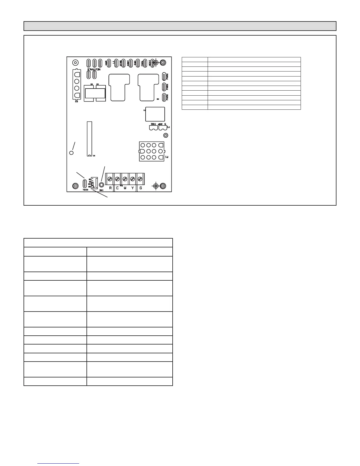
Ignition Control
FIGURE 59
Integrated Control Diagnostic Codes
DIAGNOSTIC CODES
LED Status Description
LED Off
No power to control or control
harware fault detected.
LED On Normal operation.
1 Flash
Flame present with gas vavle
de-energized.
2 Flashes
Pressure switch closed with com-
bustion air inducer e-energized.
3 Flashes
Pressure switch open with com-
bustion air inducer energized.
4 Flashes Primary limit switch open.
5 Flashes Rollout switch open.
6 Flashes Pressure switch cycle lockout.
7 Flashes Lockout, burners fail to light.
8 Flashes
Lockout, buners lost ame too
many times.
9 Flashes Line voltage polarity incorrect.
Note - This control is equipped with a push button switch
for diagnostic code recall. The control stores the last 5
fault codes in non-volatile memory. The most recent fault
code is ashed rst, the oldest fault code is ashed last.
There is a 2 second pause between codes. When the
push button switch is pressed for less than 5 seconds, the
control will ash the stored fault codes when the switch is
released. The fault code history may be cleared by press-
ing the push button switch for more than 5 seconds.
(Automatic Hot Surface Ignition System)
BLOWER OFF
DELAY JUMPER
PUSH BUTTON
LED
TWIN
TERMINAL DESIGNATIONS
HUM
LINE
XFMR
EAC
COOL
HEAT
PARK
CONT
NEUTRALS
Humidifier (120VAC)
Input (120VAC)
Transformer (120VAC)
Indoor Air Qality Accessory Air Cleaner (120VAC)
Blower - Cooling Speed (120VAC)
Blower - Heating Speed (120VAC)
Dead terminals to park alternate spd taps
Continuous blower
Neutral terminals (120VAC)
TWIN
Twinning Terminal (24VAC)
 Loading...