Page 22
8 - After assembly, wipe excess cement from pipe at end
of fitting socket. A properly made joint will show a
bead around its entire perimeter. Any gaps may indi
cate an improper assembly due to insufficient sol
vent.
9 - Handle joints carefully until completely set.
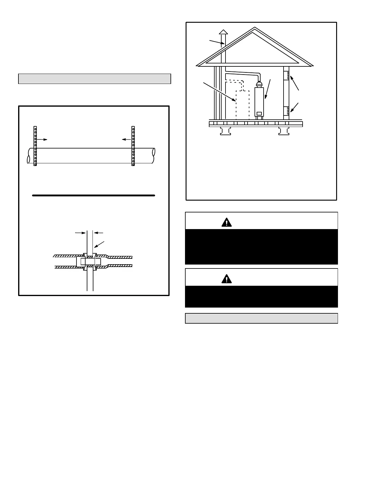
Venting Practices
FIGURE 20
* See table 9 for allowable pipe.
Piping Suspension Guidelines
NOTE - Isolate piping at the point where it exits the outside wall or
roof in order to prevent transmission of vibration to the structure.
SCHEDULE 40
PVC - 5'
all other pipe* - 3'
Wall
inside outside
24” maximum
3/4” minimum
Wall Thickness Guidelines
6. In areas where piping penetrates joists or interior
walls, hole must be large enough to allow clearance on
all sides of pipe through center of hole using a hanger.
7. When furnace is installed in a residence where unit is
shut down for an extended period of time, such as a va
cation home, make provisions for draining condensate
collection trap and lines.
Exhaust Piping (Figures 24 and 25)
Route piping to outside of structure. Continue with installa
tion following instructions given in piping termination sec
tion.
CHIMNEY
OR GAS
VENT
(Check sizing
for water
heater only)
FURNACE
(Replaced
by ML193)
WATER
HEATER
OPENINGS
(To Adjacent
Room)
If an ML193UHE furnace replaces a furnace which
was commonly vented with another gas appliance,
the size of the existing vent pipe for that gas ap
pliance must be checked. Without the heat of the
original furnace flue products, the existing vent pipe
is probably oversized for the single water heater or
other appliance. The vent should be checked for
proper draw with the remaining appliance.
FIGURE 21
REPLACING FURNACE THAT
WAS PART OF A COMMON
VENT SYSTEM
CAUTION
Do not discharge exhaust into an existing stack or
stack that also serves another gas appliance. If verti
cal discharge through an existing unused stack is re
quired, insert PVC pipe inside the stack until the end
is even with the top or outlet end of the metal stack.
CAUTION
The exhaust vent pipe operates under positive pres
sure and must be completely sealed to prevent leak
age of combustion products into the living space.
Vent Piping Guidelines
NOTE - Lennox has approved the use of DuraVent
®
and Cen
trotherm manufactured vent pipe and terminations as an option
to PVC. When using the PolyPro
®
by DuraVent or InnoFlue
®
by
Centrotherm venting system the vent pipe requirements stated
in the unit installation instruction – minimum & maximum vent
lengths, termination clearances, etc. – apply and must be fol
lowed. Follow the instructions provided with PoyPro by Du
raVent and InnoFlue by Centrotherm venting system for as
sembly or if requirements are more restrictive. The PolyPro by
Duravent and InnoFlue by Centrotherm venting system must
also follow the uninsulated and unconditioned space criteria
listed in table 14.
 Loading...