Page 43
G-Flame Signal
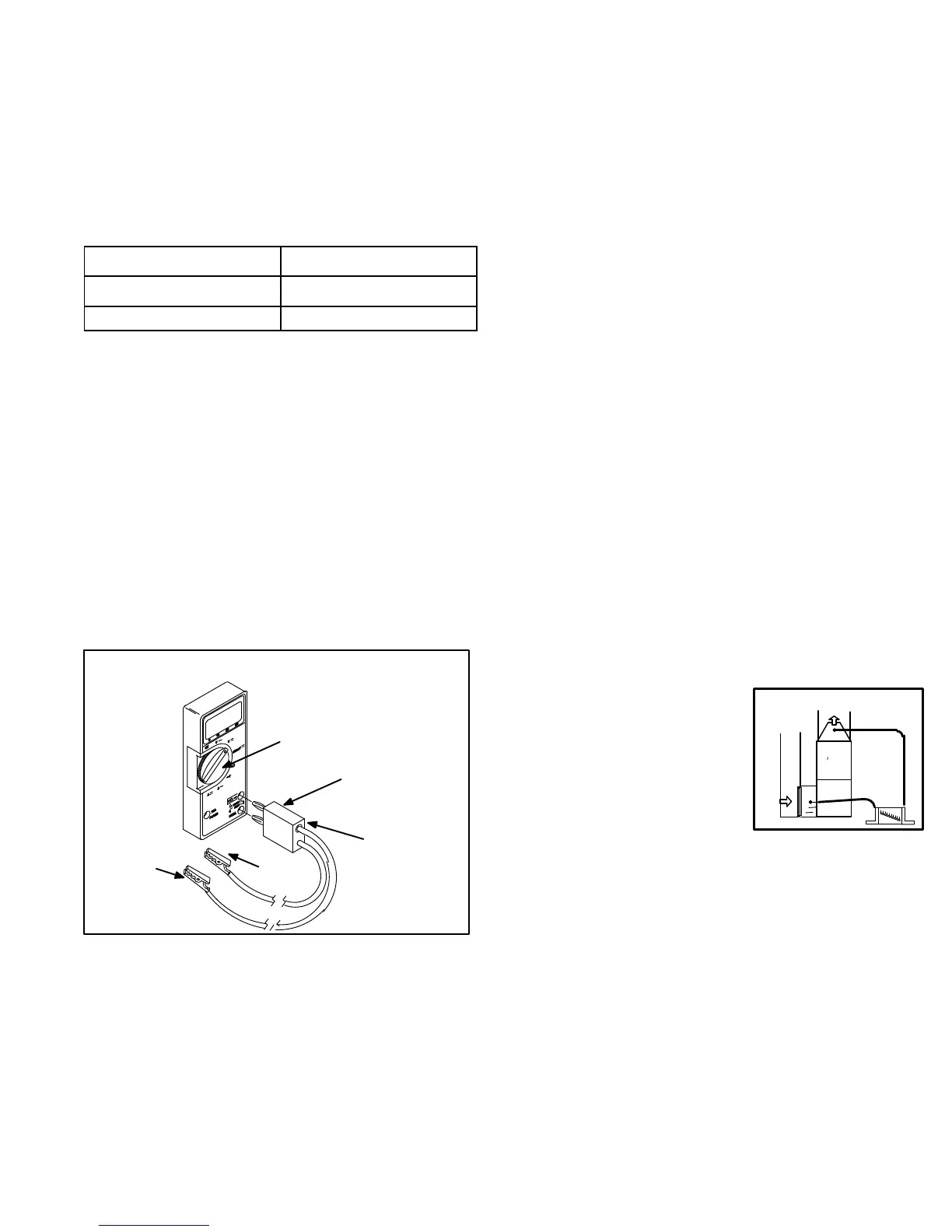
A transducer (Part #78H5401 available from Lennox Re
pair Parts) is required to measure flame signal if meter
used will not read a low micro amp signal. Seefigure56.
The transducer converts microamps to volts on a 1:1 con
version. Flame signal is shown in table 23. A digital readout
meter must be used. The transducer plugs into most me
ters.
TABLE 23
Normal Flame Signal
1.50 Microamps
Low Flame Signal
1.40 Microamps
Drop Out Signal = 0.50 Microamps
To Measure Flame Signal:
1 - Set the volt meter to the DC voltage scale. Insert trans
ducer into the VDC and common inputs. Observe cor
rect polarities. Failure to do so results in negative (-)
values.
2 - Turn off supply voltage to control.
3 - Disconnect integrated control flame sensor wire from
the flame sensor.
4 - Connect (-) lead of the transducer to flame sensor.
5 - Connect (+) lead of transducer to the integrated control
sensor wire.
6 - Turn supply voltage on and close thermostat contacts
to cycle system.
7 - When main burners are in operation for two minutes,
take reading. Remember 1 DC volt = 1 DC microamp.
SET DIAL TO
MEASURE VDC
(+)
(-)
(-) TO
FLAME
SENSOR
NOTE-MUST USE DIGITAL METER
RED COLLAR
INDICATES
POSITIVE
LEAD
(+) TO
INTE
GRATED
CONTROL
SENSOR
WIRE
FIGURE 56
TRANSDUCER
PART #78H5401
V-TYPICAL OPERATING CHARACTERISTICS
A-Blower Operation and Adjustment
1 - Blower operation is dependent on thermostat control
system.
2 - Generally, blower operation is set at thermostat sub
base fan switch. With fan switch in ON position, blower
operates continuously. With fan switch in AUTO posi
tion, blower cycles with demand or runs continuously
while heating or cooling circuit cycles.
3 - Depending on the type of indoor thermostat, blower
and entire unit will be off when the system switch is in
OFF position.
B-Temperature Rise
Temperature rise depends on unit input, blower speed,
blower horsepower and static pressure as marked on the
unit rating plate. The blower speed must be set for unit op
eration within the range of “TEMP. RISE °F” listed on the
unit rating plate.
To Measure Temperature Rise:
1 - Place plenum thermometers in the supply and return
air plenums. Locate supply air thermometer in the first
horizontal run of the plenum where it will not pick up ra
diant heat from the heat exchanger.
2 - Set thermostat for heat call.
3 - After plenum thermometers have reached their high
est and steadiest readings, subtract the two readings.
The difference should be in the range listed on the unit
rating plate. If the temperature is too low, decrease
blower speed. If temperature is too high, first check the
firing rate. Provided the firing rate is acceptable, in
crease blower speed to reduce temperature.
To change existing heat tap, turn off power then switch out
speed tap with tap connected to ”PARK” . See unit diagram
for blower motor tap colors for each speed.
C-External Static Pressure
1 - Tap locations shown in figure 57.
2 - Punch a 1/4” diameter hole
in supply and return air ple
nums. Insert manometer
hose flush with inside edge
of hole or insulation. Seal
around the hose with perma
gum. Connect the zero end
of the manometer to the dis
charge (supply) side of the system. On ducted sys
tems, connect the other end of manometer to the return
duct as above.
3 - With only the blower motor running and the evaporator
coil dry, observe the manometer reading. Adjust blow
er motor speed to deliver the air desired according to
the job requirements.
4 - External static pressure drop must not be more than
0.5” W.C. in the heating mode and must not exceed
0.6” W.C in the cooling mode.
5 - Seal the hole when the check is complete.
STATIC PRESSURE
TEST
+
-
FIGURE 57
 Loading...