8
Securing Outdoor Unit to Slab, Frame, or Rails
If the outdoor unit is installed on a eld-provided slab or
frame, use lag bolts or equivalent to secure the outdoor
unit to the slab or frame.
Four Field-provided Anchor Bolts
Figure 13. Securing Outdoor Unit to Slab
Four Field-Provided
Anchor Bolts
Figure 14. Securing Outdoor Unit to Rails
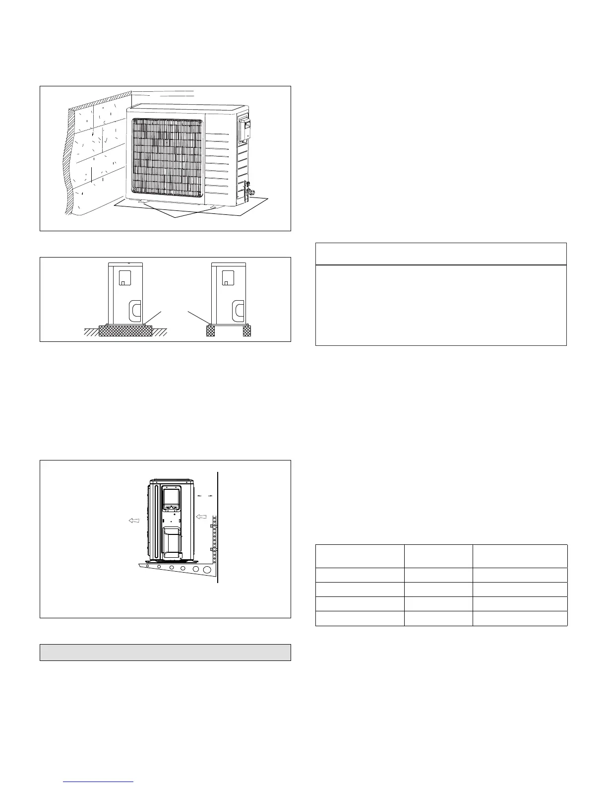
Securing Outdoor Unit To Hanging Brackets
If the outdoor unit is installed on eld-provided wall
mounting brackets, use lag bolts or equivalent to secure
the outdoor unit to the bracket. Minimum rear clearance
can be reduced to 6 inches (152 mm) when mounted
on brackets and with no obstructions on the other three
sides. Allow for condensate disposal when placing units
above one another.
Air Outlet
Air Inlet
6 in
152 mm
Figure 15. Securing Outdoor Unit to Brackets
Refrigerant Piping Connections
Field piping consists of two copper lines connecting
the outdoor unit to the indoor unit. “Table 1. Torque
Requirements” lists the connection sizes. The connections
are made using the provided brass are nuts at the end of
the refrigerant piping connections.
Both lines must be individually insulated.
1. The seal on the unit refrigerant piping connections
should remain in place until the last possible moment.
This will prevent dust or water from getting into the
refrigerant piping before it is connected.
2. CAREFULLY adjust refrigerant piping connections to
suit the application.
3. Slowly loosen one of the are nuts to release the
factory nitrogen charge from the indoor units only.
4. Remove the are nuts from the connections on the
unit and discard the seal from each of the piping
connections.
5. Slide the are nuts onto the ends of the eld-provided
refrigerant piping before using a suitable aring tool to
are the end of the copper pipe.
6. Apply recommended HFC-410A refrigerant lubricant
to the outside of the ared refrigerant lines.
IMPORTANT
The compressor in this unit contains PVE
oil (Polyvinylether). PVE oil is formulated for
hydrouorocarbon (HFC) refrigerants, such as HFC-
410A, which this system contains. While it may have
some miscibility properties with mineral-based oil and
POE oil (Polyolester), it is not recommended to mix PVE
oil with any other type of refrigerant oil.
7. Align the threaded connections with the
ared refrigerant lines. Tighten the are nuts
lightly at rst to obtain a smooth match as
illustrated in “Figure 16. Making Connections
(Male to Female Connection)” on page 9.
8. Once snug, continue another half-turn on each nut
which should create a leak-free joint. A torque wrench
may be used to tighten are nuts using “Table 3.
Flare Nut Torque Recommendations” on page 9
recommendations. Do not over-tighten a ared joint.
Flared connections should always be accessible
and must be insulated to prevent condensation.
9. After refrigerant piping has been installed and checked
for leaks, apply insulation over all ared connections.
Table 2. Refrigerant Piping and Indoor Unit
Connection Sizes
Size
(Btuh)
Liquid Line
in.
Gas Line
in.
9000 1/4 3/8
12000 1/4 1/2
18000 1/4 1/2
24000 3/8
5/8
 Loading...