69
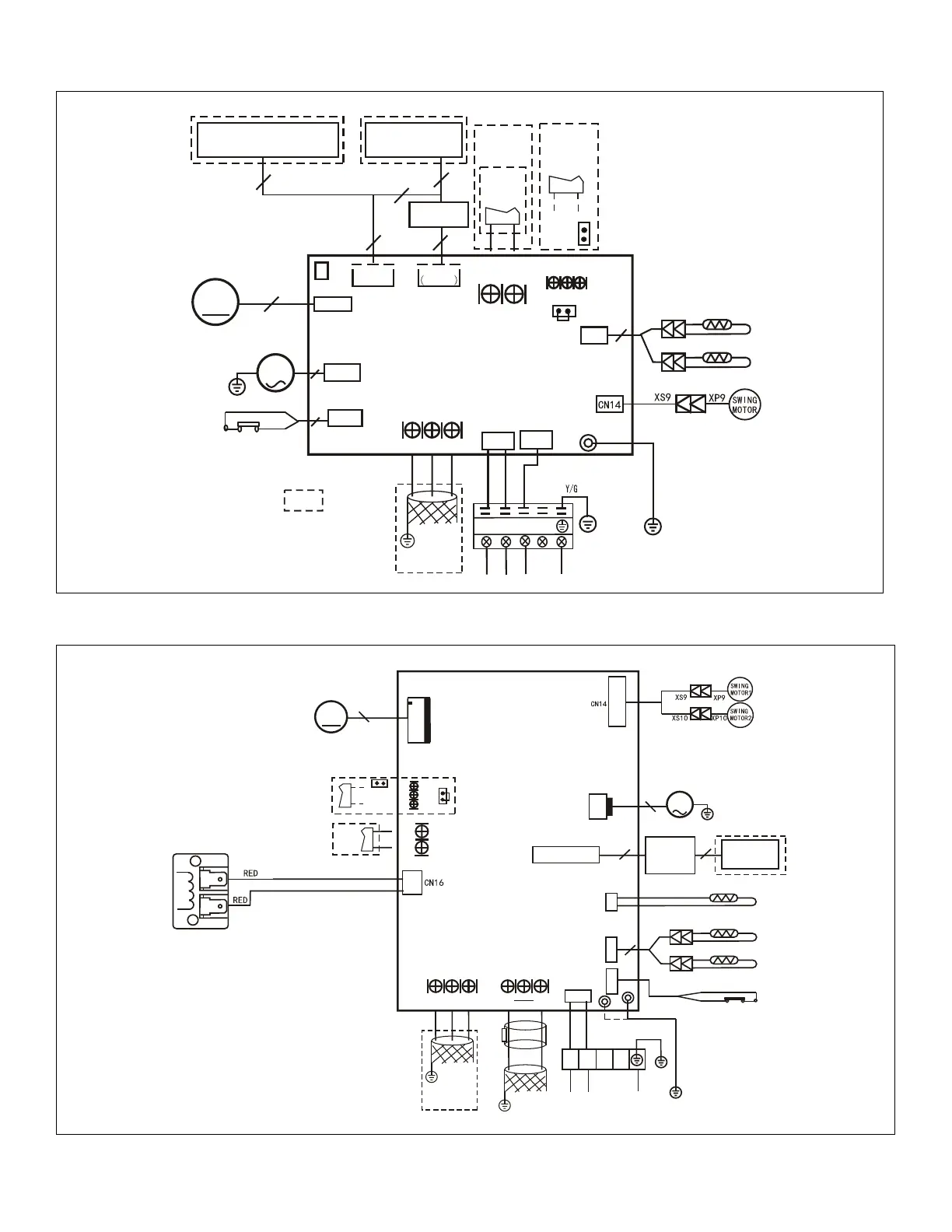
12.3. M33A and M33B Indoor Unit
1 2 3
CN13
D IS P LA Y
B O A R D
10
T2
T1
CN6
4
ROO M T EMP .SEN SOR
BL AC K
WH ITE
CN 10 A
M
PU MP
2
INDOOR UNIT
MAINBOARD
TO WIRED
CONTROLLER
5
CN23
ON - OFF
Remote
Control
CN3 3
ALA RM
Alarm
Output
CN1 5
M
Motor
5
R E D (B R O W N )
CN1
B L U E (B L A C K )
CN5
W ATE R LE VE L SW ITC H
E Y X
To LVM
Comm.Bus
P1
CN3
JR6
JR6
2
Y/G
C N 11 0
Y E L L O W
P5
CN 10
INDOOR COIL TEMP.SENSOR
Note1: Remove the JR6 jumper
for remote on /off contr ol
CN 40
TO PROGRAMMABLE
WIRED CONTROLLER
2
2
NOTE:
COMPONENT IN DASH
LINE IS OPTIONAL
OR FIELD WIRING.
Note: The programmable
wired controller and regular
wired controller use the same
wiring connector.
4
Figure 34. M33A024S4-*P Unit Wiring Diagram
Reactor
CN13
DISPLAY
BOARD
TO WIRE
CONTROLLE R
10
T2
T1
CN6
4
BLACK
WHITE
CN10(CN10A)
M
PUMP
2
INDOOR UNIT
MAINBOARD
CN23
ON - OFF
Remote
Control
CN33
ALARM
Alarm
Output
CN15
M
FAN
5
RED(BROWN)
CN1
BLUE(BLACK )
L1
L2
Y/G
CN5
WATER LEVEL SWITCH
CN2
Q E P
To CCM
Comm.Bus
CN7
T2B
INDOOR COIL OUTLET TEMP.SENSOR
POWER
P1
Y/G
CN3
JR6
JR6
To OUTDOOR
Comm.Bus
S2
S1
P4
E Y X
Ferrite beadFerr
i
t
e
bead
5
ROOM TEMP.SENSOR
INDOOR COIL TEMP.SENSOR
Note1:remove the JR6 jumper for
remote on/off control
Figure 35. M33A036S4-*P, M33A048S4-*P and M33B048S4-*P Unit Wiring Diagram
 Loading...