EasyManua.ls Logo

Lennox MPB024S4S-1P User Manual

Lennox MPB024S4S-1P
28 pages
To Next Page IconTo Next Page
To Previous Page IconTo Previous Page
Page #5 background image
5
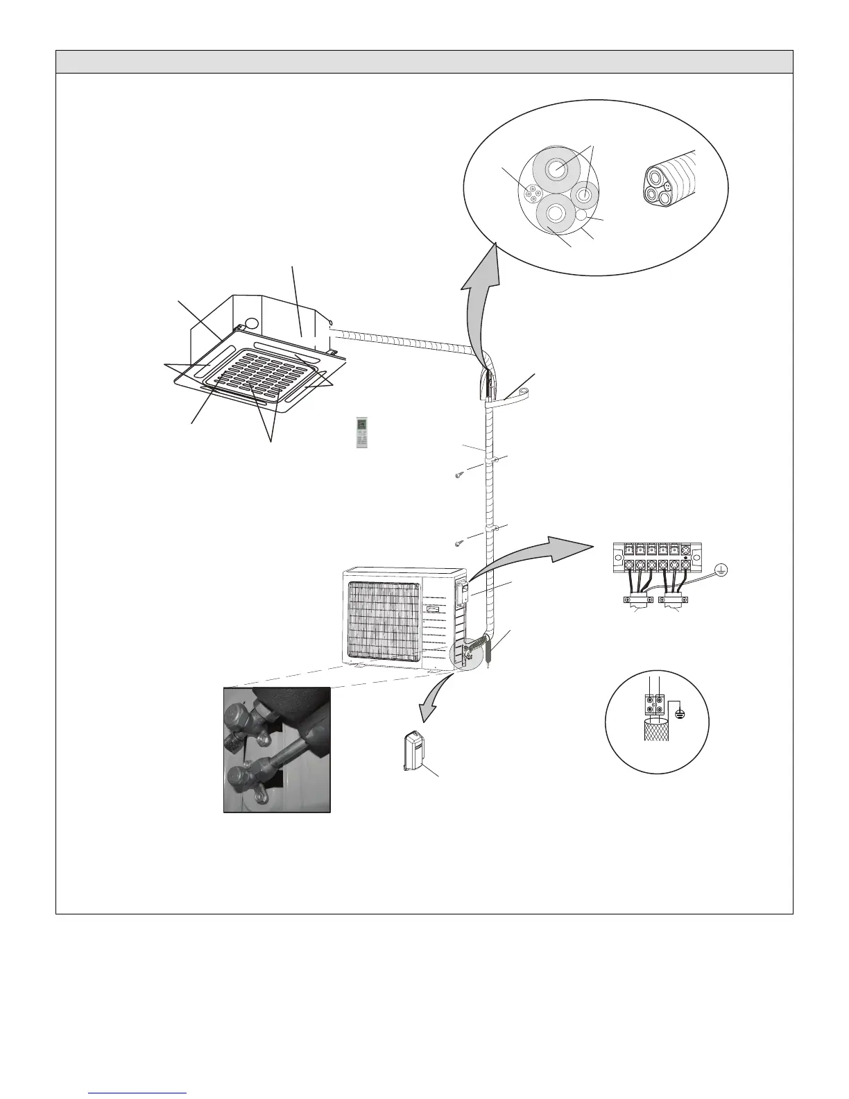
Typical System Components
Indoor Unit
Supply Air
Decorative panel
Filter
Return Air
Supply Air
Indoor unit wiring connections
(under access plate)
Wireless Remote
Control
Outdoor Unit
009-036 shown
Utility
Bundle
Wiring
Condensate drain line
(wrapped in foam insulation)
208/230V Outdoor Unit
Terminal Block
To Indoor
Unit
To Power
Supply
Access cover
for valves
Refrigerant Line Set, Condensate Line
And Indoor / Outdoor Cable
(field-provided)
Tape
IMPORTANT - The refrigerant
metering device for this system is
located in the outdoor unit. This
makes it necessary to insulate the
refrigerant lines individually to
prevent sweating.
1 2 3 L1 L2
UV-rated tape (field-provided)
Line set
(wrapped in foam insulation)
Access cover for power
and control wiring
connections
Condensate drain line
(field-provided)
Communication cable
036 and 048 only
TO INDOOR COMM. BUS
XT2
L
LEY WO
ARG
Y
S1
S2
NOTEφ
shielded wire
Use 2-conductor
Communication Cable
036 and 048 only
Liquid and vapor shut off valves
I
MPORTANT - Condensate drain line must always
be located at the bottom of the
bundle.)
Figure 1. Typical System Shown
Question and Answer IconNeed help?

Do you have a question about the Lennox MPB024S4S-1P and is the answer not in the manual?

Lennox MPB024S4S-1P Specifications

General IconGeneral
Cooling Capacity24, 000 BTU
EERUp to 11.5
RefrigerantR-410A
Voltage208/230V
Phase1
HSPFNot Applicable

Summary

General Installation Information

System Clearances

Torque Requirements and Indoor Unit Installation

Condensate Piping and Outdoor Unit Installation

Indoor Unit Condensate Piping Connections

Instructions for properly routing and connecting the condensate drain line for the indoor unit.

Outdoor Unit Protection

Securing the Outdoor Unit

Refrigerant Piping Connections

Leak Test and Evacuation

Evacuation and Wiring

Triple Evacuation Procedure

Step-by-step guide for evacuating the refrigerant system using a micron gauge.

Wiring Connections

Instructions for making all electrical power and communication wiring connections.

Unit Start-Up and Refrigerant Charge

Unit Start-Up

Steps to follow for safely energizing and starting the HVAC system.

Troubleshooting and Operation Modes

Related product manuals