16
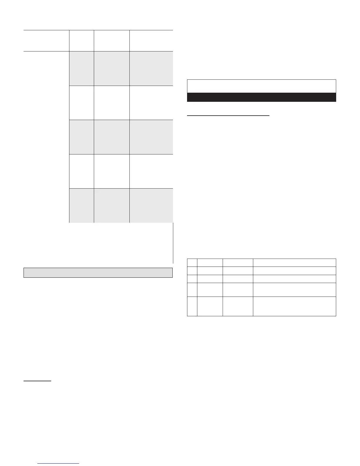
Table 4. Match-Ups
Outdoor
Model
No. of
Zones
Indoor Unit
Capacity
(Unit No.)
Line Set
Required
(Liquid x Gas)
MLA036S4M
Indoor Unit A
1/4” liq + 1/2” gas
Indoor Unit B
1/4” liq + 1/2” gas
Indoor Unit C
1/4” liq + 3/8” gas
Indoor Unit D
1/4” liq + 3/8” gas
4
009 (B)
1
1/4 in. x 3/8 in.
009 (C) 1/4 in. x 3/8 in.
009 (D) 1/4 in. x 3/8 in.
018 (A) 1/4 in. x 1/2 in.
4
009 (C) 1/4 in. x 3/8 in.
009 (D) 1/4 in. x 3/8 in.
012 (A) 1/4 in. x 1/2 in.
012 (B) 1/4 in. x 1/2 in.
4
009 (C) 1/4 in. x 3/8 in.
009 (D) 1/4 in. x 3/8 in.
012 (B) 1/4 in. x 1/2 in.
018 (A) 1/4 in. x 1/2 in.
4
009 (D) 1/4 in. x 3/8 in.
012 (A) 1/4 in. x 1/2 in.
012 (B) 1/4 in. x 1/2 in.
012 (C)
1
1/4 in. x 1/2 in.
4
012 (A) 1/4 in. x 1/2 in.
012 (B) 1/4 in. x 1/2 in.
012 (C)
1
1/4 in. x 1/2 in.
012 (D)
1
1/4 in. x 1/2 in.
1
3/8 x 1/2 in. gas pipe adaptor is required for line set connection to outdoor unit
(furnished with outdoor unit).
2
1/4 x 3/8 in. liquid pipe adaptor is required for line set connection to the 048
outdoor unit (furnished with outdoor unit).
3
1/2 x 5/8 in. gas pipe adaptor is required for line set connection to the 048
outdoor unit (furnished with outdoor unit).
4
Not a valid combination when using the MPA036S4M.
Leak Test and Evacuation
Air and moisture remaining in the refrigerant system will
have undesirable effects as indicated below:
• Pressure in the system rises
• Operating current rises
• Cooling or heating efciency drops
• Moisture in the refrigerant circuit may freeze
• Water may lead to corrosion of parts in the refrigera-
tion system
The line set between the indoor and outdoor units
must be leak tested and evacuated to remove any non-
condensables and moisture from the system.
Leak Test
Use the following procedure to test for system leaks:
1. Connect the manifold gauge set and dry nitrogen gas
cylinder to the liquid and gas service ports.
2. Open valve on nitrogen cylinder.
3. Pressurize the system per the pressure test
specications in “Table 5. Pressure Test Specications”.
4. Check that the system pressure remains stable. If
there is any movement check system for leaks.
5. After the system is found to be free of leaks:
• Close valve on nitrogen cylinder.
• Relieve the nitrogen pressure by: loosening the
charge hose connector at the nitrogen cylinder.
• When the system pressure is reduced to normal,
disconnect the hose from the cylinder.
IMPORTANT
Use only oxygen-free nitrogen (OFN).
Triple Evacuation Procedure
A Micron or Torr gauge must be used for this procedure.
1. Discharge the oxygen-free nitrogen and evacuate the
system to a reading of 8000 Microns (8 Torr) using all
service valves.
2. Break the vacuum by allowing nitrogen into the port
connections (liquid and gas line pipes) until a positive
pressure is achieved.
3. Evacuate the system to a reading of 5000 Microns (5
Torr).
4. Break the vacuum by allowing nitrogen into the port
connections (liquid and gas line pipes) until a positive
pressure is achieved
5. Evacuate the system to a minimum reading of 500
Microns (0.5 Torr).
6. For a moisture-free system, ensure the vacuum is held
without movement for a minimum of 4 hours.
7. If vacuum fails to hold, carry out steps 2 through 6 until
vacuum holds.
Table 5. Pressure Test Specications
1 3 bar 44 psig Minimum of 10 minutes
2 15 bar 220 psig Minimum of 10 minutes
3 32 bar 470 psig Minimum of 10 minutes
4 45 bar 650 psig 1 hour. Stress test to prove the
integrity of the complete installation.
5 32 bar 470 psig 24 hours. Lower system pressure
test, after conrmation No. 4 was
successfully completed.
 Loading...