Page 53
XP21
Table 20. Seven−Segment Display Alert Codes (continued)
Alert
Codes
Alarm Description Possible Causes and Clearing Alarm
E 414
The discharge line temperature is high-
er than the recommended upper limit of
279ºF.
Discharge line temperature is > 279ºF. Confirm that the system is properly charged with refrigerant.
Check system operating pressures and compare to unit charging charts in installation manual.
Confirm that the outdoor unit is clean. The alarm clears after the discharge temperature is < 225ºF.
E 415
The discharge line temperature has
been consistently higher than the rec-
ommended upper limit of 279ºF.
Discharge line high temperature error count reached 5 strikes. Confirm that the system is properly
charged with refrigerant. Check system operating pressures and compare to unit charging charts in
installation manual. Confirm that the outdoor unit is clean. The alarm clears after the discharge tem-
perature is < 225ºF. The alarm clears after a power reset.
E 416
The outdoor coil sensor is either open,
short−circuited or the temperature is out
of sensor range. As a result the outdoor
unit control will not perform any defrost
tempering.
Coil sensor being detected open or shorted, or temperature is out of coil sensor range. Outdoor unit
control will not perform demand or time/temperature defrost operation. System will still heat or cool.
Check the resistance of the coil sensor and compare to temperature resistance chart. Replace coil
sensor if needed. The alarm clears when outdoor unit control detects proper coil sensor readings or
after a power reset.
E 417
The outdoor unit discharge sensor is ei-
ther open, short−circuited or the tem-
perature is out of sensor range. As a re-
sult the outdoor unit control will not per-
form any defrost tempering.
Outdoor unit control detects open or shorted discharge sensor, or temperature that is out of
discharge sensor range. Check the resistance of the discharge sensor and compare to
temperature resistance chart − replace if needed. Reset by replacing the discharge sensor. This
fault is detected by allowing the unit to run for 90 seconds before checking discharge sensor
resistance. If the discharge sensor resistance is not within range after 90 seconds, the board will
count one fault. After 5 faults, the board will lock out. Check for proper sensor reading and
attachment to line. The alarm clears after a power reset.
E 418 There is a faulty W output circuit.
Faulty W output circuit. Confirm that the unit is not running. Check for mis−wiring. Disconnect
thermostat lines from W and verify 24VAC on the W. If 24VAC is present, replace the board.
E 419
The W output on the outdoor unit has re-
ported more than 5 errors. As a result,
the system has shutdown the outdoor
unit.
W output hardware fault count reached 5−strikes.
E 420
The heat pump defrost cycle has taken
more than 20 minutes to complete.
Defrost cycle lasts longer than 20 minutes. This alarm is applicable with non−communicating heat
pump system only. Check heat pump defrost operation. The alarm is cleared after the "W1" signal is
removed.
E 421
The W output terminal on the outdoor
unit is not wired correctly.
Voltage sensed on W and O when Y1 thermostat input is deactivated. Another device or wiring fault
is energizing W Check wiring. The alarm clears when wiring is corrected or after a power reset.
NOTE Additional codes may be found in icomfortt thermostat manual.
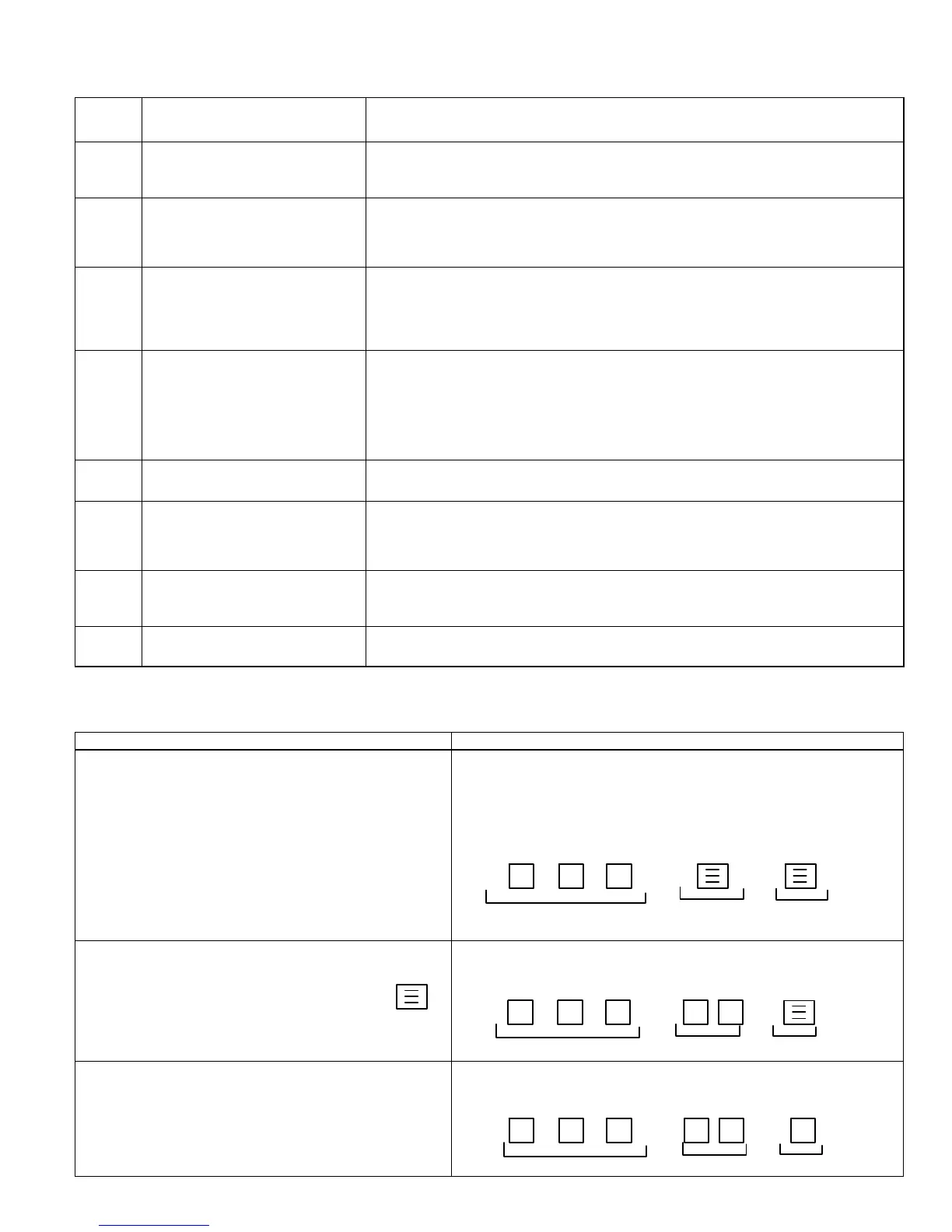
Table 21. Outdoor Control Seven−Segment Unit Status Displays
Description Example of Display
Power up / Reset: Unit type and number of stages is displayed.
Verify configuration with information published on the unit name-
plate. If the information is incorrect, refer to flow chart Manually
Configuration of Unit Type to re−configure control.
1 Stage AC: 1AC
2 Stage AC: 2AC
1 Stage AC: 1HP
1 Stage AC: 2HP
POWER−UP 7−SEGMENT DISPLAY STRING
Unit Type / Stages
No Capacity No Fan Profile
Power up / Reset following display of self−dis-
covered configuration: Unit nominal capacity is
displayed, if not programmed then three horizontal
lines and the decimal point are displayed for 2 sec-
onds.
POWER−UP 7−SEGMENT DISPLAY STRING
Unit Type / Stages
Capacity No Fan Profile
Power up nominal capacity display of an XP21−036: 36
Power up / Reset following display of nominal
capacity: Fan Profile code. (a single or two digit
number) See table 18 for applicable fan RPM pro-
file.
POWER−UP 7−SEGMENT DISPLAY STRING
Unit Type / Stages
Capacity
Fan Profile
Displays the number of the selected fan profile. 3
 Loading...