Page 30
7. Combustion Air Inducer (B6)
All SL280UHNV units use a two-stage combustion air in-
ducer to move air through the burners and heat exchang-
er during heating operation. The blower uses a 120VAC
motor. The motor operates during all heating operation
and is controlled by integrated control control A92. The in-
ducer also operates for 15 seconds before burner ignition
(prepurge) and for 5 seconds after the gas valve closes
(postpurge). The inducer operates on low speed during
fi rststage heat, then switches to high speed for second
stage heat.
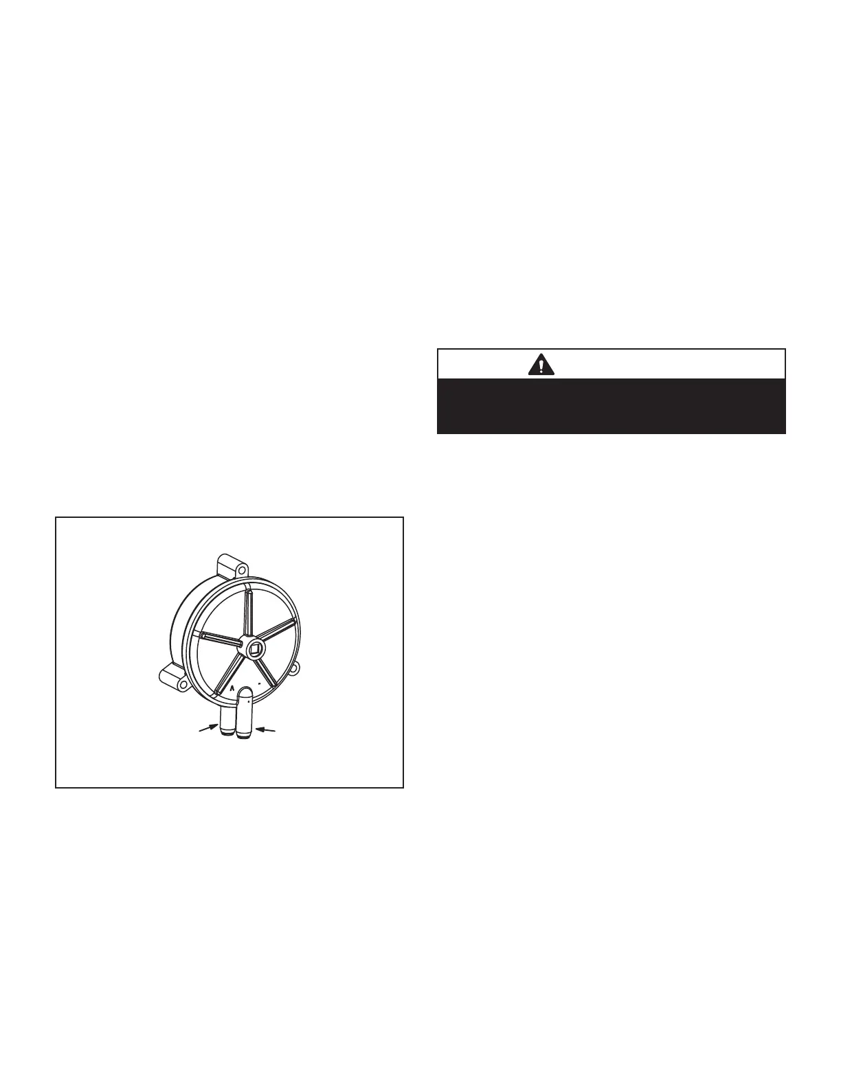
8. Combustion Air Inducer Prove Switch (S18)
SL280UHNV series units are equipped with a single com-
bustion air proving switch (fi rst and second stage) located
near the gas valve. See Figure 15. The switch is a sin-
gle-pole single-throw proving switch electrically connect-
ed to the integrated control. The purpose of the switch is
to prevent burner operation if the combustion air inducer is
not operating or if the fl ue becomes obstructed.
On heat demand (fi rst or second stage) the switch senses
that the combustion air inducer is operating. It closes a
circuit to the integrated control when pressure inside the
combustion air inducer decreases to a certain set point.
The set point is 0.20” for low heat and high heat and the
same for all SL280UHNV models. The pressure sensed
by the switch is negative relative to atmospheric pres-
sure. If the fl ue becomes obstructed during operation, the
switch senses a loss of pressure difference and opens the
circuit to the furnace control and gas valve.
COMBUSTION AIR PRESSURE SWITCH
Positive +
to air intake pipe
Negative -
to air intake
elbow
FIGURE 15
NOTE - The switch is factory set and is not fi eld adjust-
able. It is a safety shut-down control in the furnace and
must not be by-passed for any reason. If switch is closed
or bypassed, the control will not initiate ignition at start up.
II-Placement and Installation
Make sure unit is installed in accordance with installation
instructions and applicable codes.
III-Start-Up
A-Preliminary and Seasonal Checks
1 - Inspect electrical wiring, both fi eld and factory
installed for loose connections. Tighten as required.
2 - Check voltage at disconnect switch. Voltage must
be within range listed on the nameplate. If not,
consult the power company and have voltage
condition corrected before starting unit.
B-Heating Start-Up
WARNING
Shock and burn hazard.
SL280UHNV units are equipped with a hot surface
ignition system. Do not attempt to light manually.
1 - STOP! Read the safety information at the beginning
of this section.
2 - 2 - Set the thermostat to the lowest setting.
3 - Turn off all electrical power to the unit.
4 - This furnace is equipped with an ignition device
which automatically lights the burners. Do not try to
light the burners by hand.
5 - Remove the access panel.
6 - Turn switch on gas valve to OFF. Do not force. See
fi gure 16.
7 - Wait fi ve minutes to clear out any gas. If you then
smell gas, STOP! Immediately call your gas supplier
from a neighbor’s phone. Follow the gas supplier’s
instructions. If you do not smell gas go to next step.
 Loading...


