Page 14
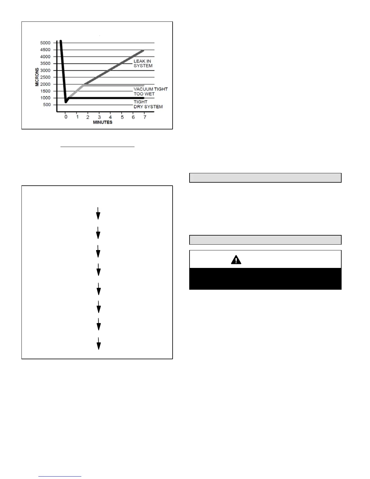
Deep Vacuum Gauge Response and
System Conditions
FIGURE 17
Triple Evacuation Method
The triple evacuation method should only be used when
system does not contain any water in liquid form and vacu
um pump is only capable of pulling down to 28 inches of
mercury (711mm Hg). Refer to figure 18 and proceed as
follows:
EVACUATE
BREAK VACUUM WITH DRY NITROGEN
WAIT
BREAK VACUUM WITH DRY NITROGEN
WAIT
EVACUATE
CHECK FOR TIGHT, DRY SYSTEM (IF IT HOLDS DEEP VACUUM)
CHARGE SYSTEM
Triple Evacuation Sequence
EVACUATE
FIGURE 18
1. Pull system down to 28 inches of mercury (711mm Hg)
and allow pump to continue operating for an additional
15 minutes.
2. Close manifold valves or valve at vacuum pump and
shut off vacuum pump.
3. Connect a nitrogen cylinder and regulator to system
and fill with nitrogen until system pressure is 2 psig.
4. Close nitrogen valve and allow system to stand for one
hour. During this time, dry nitrogen will diffuse through
out the system absorbing moisture.
5. Repeat this procedure as indicated in figure 18.
6. After the final evacuation sequence, confirm there are
no leaks in the system. If a leak is found, repeat the en
tire process after repair is made.
7. Reconnect the manifold gauge to the vacuum pump,
turn the pump on, and continue to evacuate the line set
and indoor unit until the absolute pressure does not
rise above 500 microns (29.9 inches of mercury) within
a 20-minute period after shutting off the vacuum pump
and closing the manifold gauge valves.
8. Disconnect the manifold hose from the vacuum pump
and connect it to an inverted cylinder of HFC*410A
positioned to deliver liquid refrigerant. Open the mani
fold gauge valve 1 to 2 psig in order to release the vac
uum in the line set and indoor unit.
9. Perform the following:
S Close manifold gauge valves.
S Shut off HFC*410A cylinder.
S Slowly open the service valves.
S Refer to the charging sticker on the unit to com
plete the outdoor unit installation.
Charging
The SL18XC1 unit is factory-charged with enough
HFC-410A refrigerant to accommodate a 15-foot length of
refrigerant piping. Charge should be checked and adjusted
using the tables provided on the charging procedure stick
er on the unit access panel. Detailed information is given in
the SL18XC1 Installation and Service Procedures manual,
which is available on LennoxPROS.com.
Homeowner Information
CAUTION
Before attempting to perform any service or mainte
nance, turn the electrical power to unit OFF at discon
nect switch.
In order to ensure peak performance, your system must be
properly maintained. Clogged filters and blocked airflow
prevent your unit from operating at its most efficient level.
Homeowner Maintenance
The following maintenance may be performed by the
homeowner.
S Contact a licensed professional HVAC technician to
schedule a yearly inspection and maintenance appoint
ment for your equipment.
S Check the indoor unit filter each month and replace the
filter, if necessary.
Have your Lennox dealer show you where your indoor
unit filter is located. It will be either at the indoor unit (in
stalled internal or external to the cabinet) or behind a re
turn air grille in the wall or ceiling. Check the filter monthly
and clean or replace it as needed.
Disposable filters should be replaced with a filter of the
same type and size.
S Check the indoor unit drain line for obstructions monthly
during the cooling season.
The indoor evaporator coil is equipped with a drain pan
 Loading...