EasyManua.ls Logo

Lennox XC21 User Manual

Lennox XC21
51 pages
To Next Page IconTo Next Page
To Previous Page IconTo Previous Page
Page #6 background image
Page 6
506518−01
Recovering Refrigerant from Existing System
SERVICE DISCONNECT
SWITCH
Disconnect all power to the existing outdoor unit at the disconnect
switch or main fuse box/breaker panel.
DISCONNECT POWER
CONNECT MANIFOLD GAUGE SET
MANIFOLD GAUGES
RECOVERY MACHINE
CLEAN RECOVERY
CYLINDER
OUTDOOR UNIT
HIGH
LOW
Connect a gauge set, clean recovery cylinder and a recovery
machine to the service ports of the existing unit. Use the
instructions provided with the recovery machine to make the
connections.
METHOD 1:
Us this method if the existing outdoor unit is not equipped with shut−off valves, or if the unit is not operational and you plan to use the existing
HCFC−22 to flush the system.
Remove all HCFC−22 refrigerant from the existing system. Check gauges after shutdown to confirm that the entire system is completely void of
refrigerant.
METHOD 2:
Use this method if the existing outdoor unit is equipped with manual shut−off valves, and you plan to use new HCFC−22 refrigerant to flush the
system.
The following devices could prevent full system charge recovery into the outdoor unit:
S Outdoor unit’s high or low−pressure switches (if applicable) when tripped can cycle the compressor OFF.
S Compressor can stop pumping due to tripped internal pressure relief valve.
S Compressor has internal vacuum protection that is designed to unload the scrolls (compressor stops pumping) when the pressure ratio meets
a certain value or when the suction pressure is as high as 20 psig. (Compressor suction pressures should never be allowed to go into a vacuum.
Prolonged operation at low suction pressures will result in overheating of the scrolls and permanent damage to the scroll tips, drive bearings and
internal seals.)
Once the compressor can not pump down to a lower pressure due to one of the above system conditions, shut off the vapor valve. Turn OFF the
main power to unit and use a recovery machine to recover any refrigerant left in the indoor coil and line set.
Perform the following task:
A Start the existing HCFC−22 system in the cooling mode and close the liquid line valve.
B Use the compressor to pump as much of the existing HCFC−22 refrigerant into the outdoor unit until the outdoor system is full. Turn the outdoor unit
main power OFF and use a recovery machine to remove the remaining refrigerant from the system.
NOTE  It may be necessary to bypass the low pressure switches (if equipped) to ensure complete refrigerant evacuation.
C When the low side system pressures reach 0 psig, close the vapor line valve.
D Check gauges after shutdown to confirm that the valves are not allowing refrigerant to flow back into the low side of the system.
RECOVERING
REFRIGERANT FROM SYSTEM
Remove existing HCFC−22 refrigerant using one of the following procedures:
RECOVERING REFRIGERANT
IMPORTANT  Some system configurations may contain higher than normal refrigerant charge due to either large internal coil volumes,
and/or long line sets.
1
2
3

Other manuals for Lennox XC21

Question and Answer IconNeed help?

Do you have a question about the Lennox XC21 and is the answer not in the manual?

Lennox XC21 Specifications

General IconGeneral
SEER Ratingup to 21.00
Sound Ratingas low as 69 dB
RefrigerantR-410A
Energy Star CertifiedYes
Compressor TypeTwo-Stage
Cooling Capacity (BTU/h)24000-54000
Warranty10-Year Limited Warranty on compressor

Summary

Notice and Warnings

Important Notice

Important advisory about thermostat requirements and system setup.

Installation Warning

Warning about improper installation causing injury, loss of life, or property damage.

General Unit Design

Unit design for HFC-410A refrigerant and requirement for approved indoor air handler.

Model Number Identification

Torque Requirements and Service Valves

Torque Requirements

Information on proper tightening of fasteners and torque values for components.

Using Manifold Gauge Set

Guidelines for using manifold gauge sets with HFC-410A refrigerant systems.

Operating Service Valves

Describes the function of liquid and vapor line service valves for system operations.

Service Valves

Accessing and Operating Service Valves

Procedures for accessing and operating service valves.

Reinstall Stem Cap

Procedure for reinstalling stem caps on service valves.

Recovering Refrigerant from Existing System

New Outdoor Unit Placement

Placing Unit on Slab

Instructions for placing the unit on a slab, including slope tolerance.

Elevating the Unit

Methods for elevating the unit using support feet and threaded adapters.

Stabilizing Unit on Uneven Surfaces

Roof Mounting

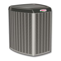
Guidelines for installing the unit on a roof, including minimum clearance.

Unit Stabilization Methods

Slab Side Mounting

Procedure for mounting the unit to a concrete or wood slab using stabilizing brackets.

Deck Top Mounting

Procedure for mounting the unit to a deck top using stabilizing brackets.

Removing and Installing Panels

New or Replacement Line Set

Line Set Installation

Brazing Connections

Flushing the System

Component Removal Procedures

Procedures for removing fixed orifice and check expansion valve components.

Flushing Setup and Procedure

Setup for flushing and the line set flushing procedure.

Typical Check Expansion Valve Installation Procedure

Sensing Bulb Installation

Instructions for installing the sensing bulb for temperature measurement.

Equalizer Line Installation

Instructions for installing the equalizer line.

Installing Isolation Grommets

Leak Testing the System

Connect Gauge Set

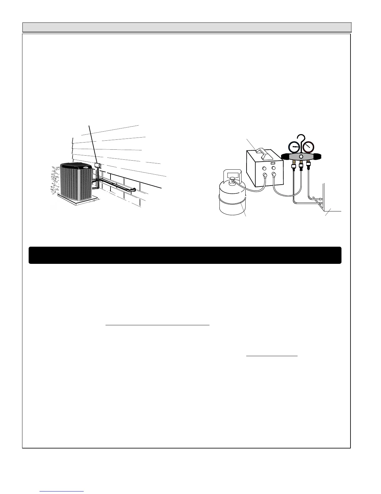
Steps for connecting the manifold gauge set for leak testing.

Test for Leaks

Procedure to test the system for leaks using refrigerant and nitrogen.

Evacuating the System

Connect Gauge Set

Connecting the gauge set and vacuum pump for evacuation.

Evacuate the System

Steps to evacuate the system to the required micron levels.

Electrical Installation

Size Circuit and Install Disconnect Switch

Instructions for sizing circuits and installing disconnect switches.

24VAC Transformer

Information regarding the 24VAC transformer for control power.

Install Thermostat

Guidelines for installing the room thermostat at the correct location.

Route Control Wires

Non-Communicating Wiring

Specific instructions for routing control wires in non-communicating applications.

Communicating Wiring

Specifications for routing control wires in communicating applications.

Route High Voltage and Ground Wires

Instructions for routing high voltage and ground wires, and connecting conduit.

A175 Main Control Jumpers and Terminals

Field Test Pins (E33)

Description of Field Test Pins (E33) and their function.

DS11 and DS14 LED Alert Codes

Explains the LED alert codes for DS11 and DS14 on the A175 main control.

DS15 and DS13 LED Compressor Alert Codes

Explains the LED alert codes for DS15 and DS13 on the A175 main control.

Field Control Wiring

Servicing Units Delivered Void of Charge

Unit Start-Up

Steps and checks required before starting up the unit.

System Refrigerant

Procedures for testing, charging, and verifying system refrigerant levels.

Gauge Set Connections for Testing and Charging

Instructions for connecting the gauge set for system testing and charging.

Adding or Removing Refrigerant

Airflow Check

Checking indoor airflow using the Delta-T process and chart.

Charge Calculation Methods

Weigh In Method

Method for charging the system using the weigh-in process.

Determine Correct Charge Method

Guidance on selecting the correct charge method (TXV, Approach, Weigh-in).

Calculate System Charge

Calculating the total refrigerant charge for an empty system.

Approach Method

Subcooling Method

Operating and Temperature Pressures

System Operation

Coil Temperature Sensor

Information on the coil temperature sensor (or lack thereof) and its function.

Testing Ambient and Discharge Line Temperature Sensors

Procedures for testing ambient and discharge line temperature sensors.

E33 Jumper (Test) Pins

A175 Main Control LED System Status and Alert Codes

Resetting LED Alert Codes

Methods for resetting LED alert codes manually or automatically.

Maintenance Procedures

A175 Main Control Unit Size Code Configuration

Procedure for setting the unit size code on the A175 main control.

A177 Fan Motor Control LED Codes, Jumper Settings and Sequence of Operation

Explains LED codes, jumper settings, and operation sequences for the A177 fan motor control.

B4 Fan Motor Test

B4 Fan Motor Test Procedure

Procedure for testing the B4 fan motor operation using a 9V battery.

Fan Motor Surge Protection and Maintenance

Fan Motor Surge Protection

Explanation of the fan motor surge protector (MOV) and how to check it.

Outdoor Unit Maintenance

Maintenance procedures for the outdoor unit, including inspection and cleaning.

Indoor Unit and Coil Maintenance

Procedures for maintaining indoor unit components like filters and condensate lines.

Homeowner Maintenance Tasks

Outdoor Coil Homeowner Maintenance

Homeowner guidance on outdoor coil maintenance and inspection.

General Homeowner Maintenance

General homeowner checks for system operation and maintenance.

Checklists

Two-Stage Modulation Compressors Field Operational Checklist

Checklist for verifying compressor and fan motor performance during Y1 and Y2 demand.

XC21 Start-Up and Performance Checklist

Start Up Checks

Checks to perform before initiating system start-up.

Cooling Mode

Performance checks and measurements for the unit in cooling mode.

Related product manuals