Page 18
XP16
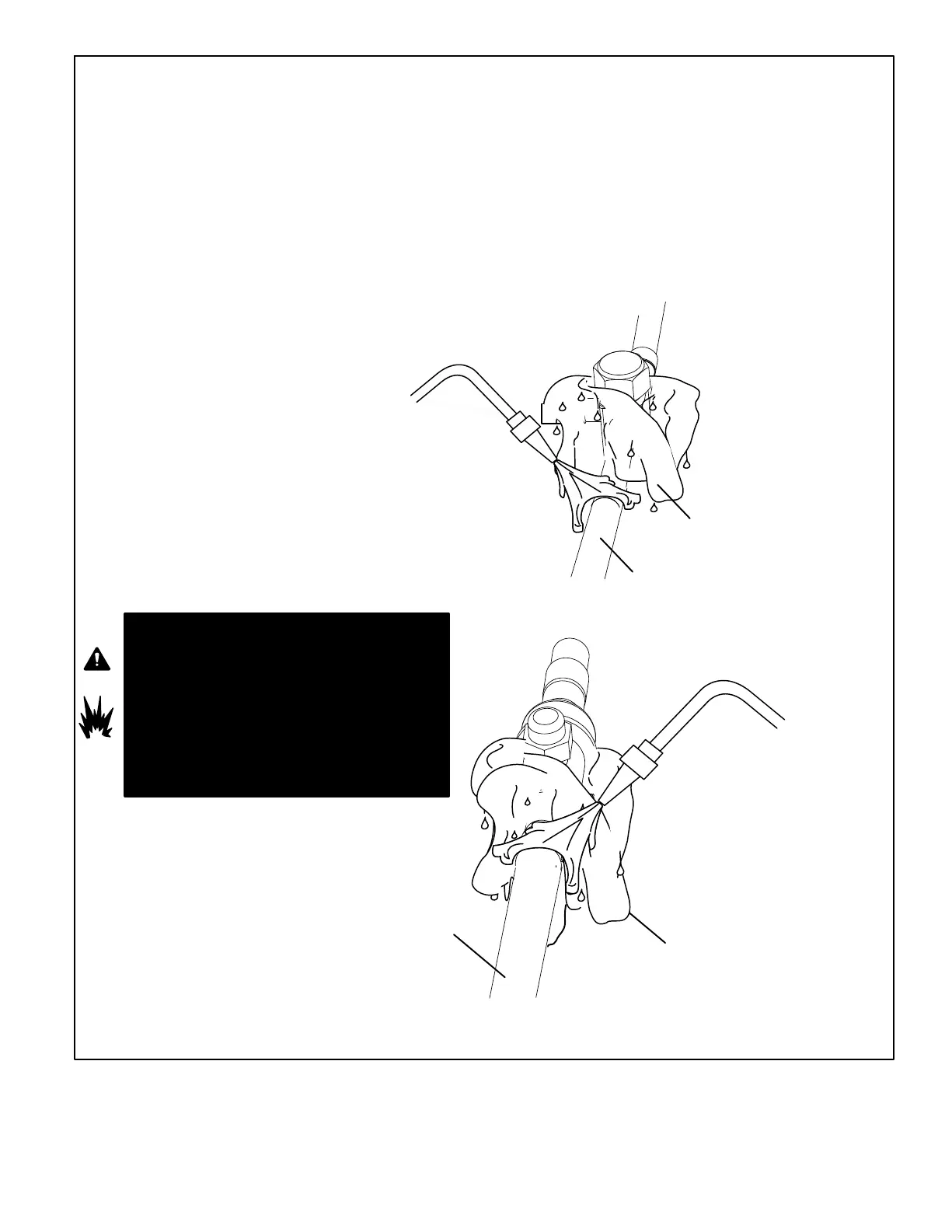
WHEN BRAZING LINE SET TO
SERVICE VALVES, POINT FLAME
AWAY FROM SERVICE VALVE.
LIQUID LINE SERVICE VALVE
LIQUID LINE
BRAZE LINE SET
Wrap both service valves with water saturated cloths as illustrated here and as mentioned in step 4, before brazing to line set. Water
saturated cloths must remain water saturated throughout the brazing and cool−down process.
WATER SATURATED
CLOTH
IMPORTANT Allow braze joint to cool. Apply
additional water saturated cloths to help cool brazed
joint. Do not remove water saturated cloths until piping
has cooled. Temperatures above 250ºF will damage
valve seals.
6
SUCTION / VAPOR LINE
WATER SATURATED
CLOTH
SUCTION / VAPOR LINE
SERVICE VALVE
After all connections have been brazed, disconnect manifold gauge set from service ports. Apply additional water saturated cloths to both
services valves to cool piping. Once piping is cool, remove all water saturated cloths. Refer to the unit installation instructions for the next
step in preparing the unit.
WHEN BRAZING LINE SET TO
SERVICE VALVES, POINT FLAME
AWAY FROM SERVICE VALVE.
PREPARATION FOR NEXT STEP
7
WARNING
1. FIRE, PERSONAL INJURY, OR PROPERTY
DAMAGE will result if you do not wrap a water
saturated cloth around both liquid and suction line
service valve bodies and copper tube stub while
brazing in the line set! The braze, when complete,
must be quenched with water to absorb any
residual heat.
2. Do not open service valves until refrigerant lines
and indoor coil have been leak−tested and
evacuated. Refer to procedures provided in this
supplement.
WRAP SERVICE VALVES
To help protect service valve seals during brazing, wrap water saturated cloths around service valve bodies and copper tube stubs. Use
additional water saturated cloths underneath the valve body to protect the base paint.
4
FLOW NITROGEN
Flow regulated nitrogen (at 1 to 2 psig) through the refrigeration gauge set into the valve stem port connection on the liquid service valve
and out of the suction / vapor valve stem port. See steps 3A, 3B and 3C on manifold gauge set connections
5
Figure 10. Brazing Procedures (continued)
 Loading...