Page 38
XP16
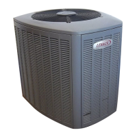
RESISTANCE (OHMS)
TEMPERATURE (ºF)
5750
7450
9275
11775
15425
19975
26200
34375
46275
62700
100
90
80
70
60
50
40
30
20
10
0
10000 30000 50000 70000 90000
85300
Figure 21. Temperature/Resistance Chart
(Ambient and Coil Sensors)
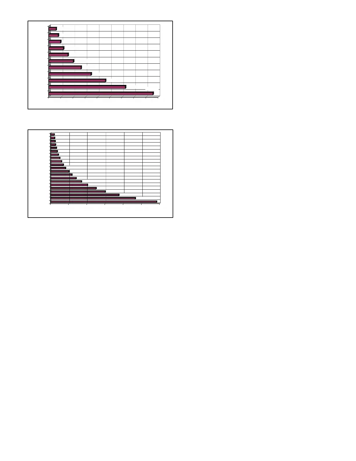
RESISTANCE (OHMS)
TEMPERATURE (ºF)
200
325
250
425
600
825
1175
1700
2500
3750
5825
300
280
260
240
220
200
180
160
140
120
100
1000 2000 50004000 60003000
4650
3000
2025
1400
1000
700
225
275
375
500
Figure 22. Temperature/Resistance Chart
(Discharge Sensor)
Coil SensorThe coil temperature sensor considers
outdoor temperatures below −35°F (−37°C) or above 120°F
(48°C) as a fault. If the coil temperature sensor is detected
as being open, shorted or out of the temperature range of the
sensor, the board will not perform demand or
time/temperature defrost operation and will display the
appropriate fault code. Heating and cooling operation will be
allowed in this fault condition.
High Discharge Line SensorIf the discharge line
temperature exceeds a temperature of 285°F (140°C)
during compressor operation, the board will de−energize the
compressor contactor output (and the defrost output, if
active). The compressor will remain off until the discharge
temperature has dropped below 225°F (107°C) and the
5-minute anti−short cycle delay has been satisfied. This
sensor has two fault and lockout codes:
1. If the board recognizes five high discharge line
temperature faults during a single (Y1) compressor
demand, it reverts to a lockout mode and displays the
appropriate code. This code detects shorted sensor or
high discharge temperatures. Code on board is
Discharge Line Temperature Fault and Lockout.
2. If the board recognizes five temperature sensor range
faults during a single (Y1) compressor demand, it
reverts to a lockout mode and displays the appropriate
code. The board detects open sensor or
out-of-temperature sensor range. This fault is detected
by allowing the unit to run for 90 seconds before
checking sensor resistance. If the sensor resistance is
not within range after 90 seconds, the board will count
one fault. After five faults, the board will lockout. Code
on board is Discharge Sensor Fault and Lockout.
The discharge line sensor, which covers a range of 150°F
(65°C) to 350°F (176°C), is designed to mount on a ½"
refrigerant discharge line.
NOTE − Within a single room thermostat demand, if 5−strikes
occur, the board will lockout the unit. Defrost board 24 volt
power R must be cycled OFF or the TEST pins on board
must be shorted between 1 to 2 seconds to reset the board.
Defrost Temperature Termination Shunt (Jumper)
PinsThe defrost board selections are: 50, 70, 90, and
100°F (10, 21, 32 and 38°C). The shunt termination pin is
factory set at 50°F (10°C). If temperature shunt is not
installed, default termination temperature is 90°F (32°C).
DELAY MODE
The defrost board has a field−selectable function to reduce
occasional sounds that may occur while the unit is cycling in
and out of the defrost mode. When a jumper is installed on
the DELAY pins, the compressor will be cycled off for 30
seconds going in and out of the defrost mode. Units are
shipped with jumper installed on DELAY pins.
NOTE − The 30 second off cycle is NOT functional when
jumpering the TEST pins.
OPERATIONAL DESCRIPTION
The defrost control board has three basic operational
modes: normal, defrost, and calibration.
D Normal ModeThe demand defrost board monitors
the O line, to determine the system operating mode
(heat/cool), outdoor ambient temperature, coil
temperature (outdoor coil) and compressor run time to
determine when a defrost cycle is required.
D Calibration ModeThe board is considered
uncalibrated when power is applied to the board, after
cool mode operation, or if the coil temperature exceeds
the termination temperature when it is in heat mode.
Calibration of the board occurs after a defrost cycle to
ensure that there is no ice on the coil. During calibration,
the temperature of both the coil and the ambient sensor
are measured to establish the temperature differential
which is required to allow a defrost cycle.
D Defrost ModeThe following paragraphs provide a
detailed description of the defrost system operation.
D Test Mode See Figure 23.
Each test pin shorting will result in one test event. For
each TEST the shunt (jumper) must be removed for at least
one second and reapplied. Refer to flow chart (figure 23) for
TEST operation.
Note: The Y1 input must be active (ON) and the O room
thermostat terminal into board must be inactive.
DETAILED DEFROST SYSTEM OPERATION
The demand defrost control board initiates a defrost cycle
based on either frost detection or time.
Frost DetectionIf the compressor runs longer than 30
minutes and the actual difference between the clear coil and
frosted coil temperatures exceeds the maximum difference
allowed by the control, a defrost cycle will be initiated.
 Loading...