Page 21
XP19 SERIES
System Operations19
The outdoor unit and indoor blower cycle on demand from
the room thermostat. When the thermostat blower switch
is in the ON position, the indoor blower operates
continuously.
THERMOSTAT OPERATION
Some indoor thermostats incorporate isolating contacts
and an emergency heat function (which includes an amber
indicating light). The thermostat is not included with the
unit and must be purchased separately.
EMERGENCY HEAT (AMBER LIGHT)
An emergency heat function is designed into some room
thermostats. This feature is applicable when isolation of the
outdoor unit is required, or when auxiliary electric heat is
staged by outdoor thermostats. When the room thermostat is
placed in the emergency heat position, the outdoor unit
control circuit is isolated from power and field-provided relays
bypass the outdoor thermostats. An amber indicating light
simultaneously comes on to remind the homeowner that the
unit is operating in the emergency heat mode.
Emergency heat is usually used during an outdoor unit
shutdown, but it should also be used following a power
outage if power has been off for over an hour and the
outdoor temperature is below 50°F (10°C). The system
should be left in the emergency heat mode at least six
hours to allow the crankcase heater sufficient time to
prevent compressor slugging.
FILTER DRIER
The unit is equipped with a large−capacity biflow filter drier
which keeps the system clean and dry. If replacement is
necessary, order another of like design and capacity.
Lennox System Operation Monitor
(LSOM) (100034−1)20
The diagnostic indicator detects the most common fault
conditions in the air conditioning system. When an
abnormal condition is detected, the module communicates
the specific condition through its ALERT and TRIP lights.
The module is capable of detecting both mechanical and
electrical system problems.
IMPORTANT
This monitor does not provide safety protection.
The is a monitoring device only and cannot control
or shut down other devices.
LSOMLED FUNCTIONS
The LSOM LED functions are described as follows:
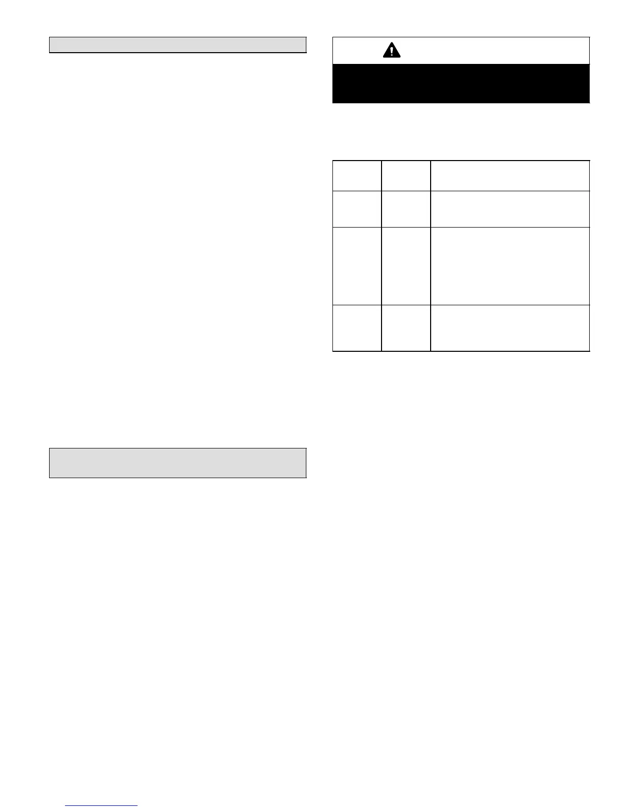
Table 10. LED Functions
Label LED
Color
Function
Power Green Indicates voltage within the range of
19−28VAC is present at the system
monitor power connection.
Alert Yellow Communicates an abnormal system
condition through a unique flash code.
The alert LED flashes a number of
times consecutively; then pauses;
then repeats the process. This
consecutive flashing correlates to a
particular abnormal condition.
Trip Red Indicates there is a demand signal
from the thermostat but no current to
the compressor is detected by the
module.
Refer to Table 12 for the complete explanation of
troubleshooting codes.
RESETTING ALERT CODES
Alert codes can be reset manually or automatically:
Manual Reset
Cycle the 24VAC power to LSOM off and on. After power
up, existing code will display for 60 seconds and then clear.
Manual reset can be achieve by any of the following
methods:
S Disconnecting R wire from the LSOM’s R terminal.
S Turning the indoor unit off an on again
Automatic Reset
After an alert is detected, the LSOM continues to monitor
the compressor and system. When/if conditions return to
normal, the alert code is turned off automatically.
 Loading...