Do you have a question about the Lenovo Legion T730 Series and is the answer not in the manual?
Eject button and slot for optical drive, available on selected models.
Identifies front USB ports, headset, and microphone connectors.
Button used to turn the computer on or off.
Identifies rear HDMI, USB, Ethernet ports, headset connector, and expansion slots.
Includes rubber cable tie for organization and the main power connector.
Guidelines to read before opening or repairing the computer.
Essential steps to follow before starting any component disassembly.
Instructions for removing and replacing the keyboard and mouse.
Steps for disconnecting the power cord and removing the computer cover.
Procedures for removing the front bezel and installing a new hard disk drive.
Detailed steps for removing and installing an optical drive.
Guide for removing and replacing a solid state drive.
Instructions for replacing the heat sink and fan assembly (multiple types).
Steps for installing or replacing a PCI express adapter.
Procedure for installing or replacing memory modules.
Guide for removing and installing the coin-cell battery.
Instructions for removing and installing the power supply unit.
This document serves as a user guide for the Lenovo Legion T730/T530 Series desktop computers, covering various models identified by Machine Types (MT): 90JF, 90JL, 90JU, 90JY, 90K0, 90L3, 90L4, and 90JG. Energy Star MT models include 90JF, 90JL, 90JY, and 90L3. The guide provides detailed instructions for identifying components, using the system, and performing basic maintenance, specifically focusing on the replacement of Customer Replaceable Units (CRUs).
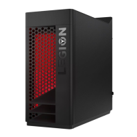
The front and top of the computer feature several user-accessible components and connectors. On the front, there is an optical drive eject button (1) and the optical drive itself (2), though these are only present on selected models. For connectivity, the front panel includes two USB 3.1 Gen 1 connectors (3) and a headset connector (4). Audio input is provided by a microphone connector (5). The power button (6) is also located on the front panel. A critical safety note emphasizes that the computer must be placed in a vertical position and that blocking air vents can lead to thermal problems.
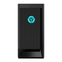
The rear panel of the Legion T730/T530 series computers varies slightly depending on the specific model (T530-28ICB, T530-28APR, T730-28ICO), but common features are present across all. All models include an HDMI-out connector (1) for video output. For data transfer, there are two USB 3.1 Gen 1 connectors (2) and two USB 3.1 Gen 2 connectors (3). Additionally, two USB 2.0 connectors (4) are available. Network connectivity is provided by an Ethernet connector (5). An audio headset connector (6) is also present. Expansion capabilities are offered through expansion card slots (7), typically used for graphic cards. A rubber cable tie (8) helps manage cables, and the power connector (9) is where the power cord is attached. A specific note advises users with two VGA monitor connectors to ensure they use the connector on the graphics adapter for optimal performance.
Before attempting any repairs or opening the computer, users are strongly advised to read the "Important safety information" sections found in the Safety, Warranty, Environment, Recycling Information Guide and Important Product Information Guide that came with the computer. If these guides are unavailable, they can be accessed online at http://www.lenovo.com/UserManuals. This emphasizes the importance of safety precautions before any internal work.
Prior to any disassembly procedure, several crucial steps must be followed to ensure safety and prevent damage. First, the power to the system and all connected peripherals must be turned off. Second, all power and signal cables should be unplugged from the computer. Finally, the system should be placed on a flat, stable surface to prevent accidental movement or falls during maintenance.
The guide lists various components that are considered Customer Replaceable Units (CRUs), meaning they can be replaced by the user. These include common peripherals and internal components:
The document then provides step-by-step instructions for replacing these CRUs, with each replacement procedure referenced by a sequence of steps. For example, replacing the hard disk drive involves following steps 3, 4, and 6, while replacing the optical drive requires steps 3, 4, and 7.
Removing the keyboard: This involves unplugging the keyboard cable from the computer. The illustrations show a USB connector being pulled out, indicating a standard wired USB keyboard.
Removing the mouse: Similar to the keyboard, this involves unplugging the mouse cable from the computer, again typically a USB connector.
Removing the power cord: This is a two-step process. First, the power cord is unplugged from the wall outlet or power strip (1). Second, the power cord is unplugged from the computer's power connector (2) at the rear.
Removing the computer cover: This procedure involves unscrewing a single screw (1) on the rear of the computer that secures the side panel. Once the screw is removed, the cover can be slid backward and then lifted off (2).
Removing the front bezel: To remove the front bezel, the computer cover must first be removed. Then, the front bezel is detached by releasing clips or tabs (1) and pulling it away from the chassis (2). This step is often necessary to access components behind the front panel.
Replacing a hard disk drive: This is a multi-step process. First, the hard drive cage might need to be released or slid out (1). The hard drive itself is then removed from its bay (2). If the drive has mounting screws or brackets, these are typically removed (3) before the old drive is replaced with a new one (4).
Replacing the optical drive: This involves releasing a latch or screw (1) that secures the optical drive. The drive is then slid out of its bay (2) and disconnected from its cables (3). The new optical drive is connected to the cables and slid back into place (4), and then secured (5).
Replacing the solid state drive: The solid state drive (SSD) is typically secured by a screw (1). After removing the screw, the SSD can be carefully pulled out of its slot (2).
Replacing the heat sink and fan assembly: This procedure is critical for CPU cooling and has multiple types depending on the specific assembly.
Replacing a PCI express adapter: This involves several steps. First, any securing mechanism, such as a clip or screw (2), for the expansion slot cover is released. The adapter's power cable (1) might need to be disconnected. The adapter is then carefully pulled out of its slot (5). A securing latch (3) might need to be pressed to release the adapter. If a bracket is involved, it might need to be removed (4). Finally, the new adapter is inserted and secured (6). A crucial note for this step is to ensure the PCI express adapter is installed with the PCI port area facing the EMI gasket with the correct orientation.
Replacing the memory module: This is a straightforward process. The retaining clips (1) on either side of the memory module slot are pushed outwards. The old memory module is then pulled out (2). The new memory module is aligned with the slot (3) and pressed down until the retaining clips snap into place (4).
Replacing the coin-cell battery: The coin-cell battery is typically held in place by a small clip. The old battery is removed by gently prying it out (1, 2). The new battery is then inserted with the correct polarity (3, 4), usually positive side up, and pressed down until it clicks into place.
Replacing a power supply: This is a more involved process. First, the power supply unit (PSU) is typically secured by screws (1) at the rear of the chassis. All cables connecting the PSU to the motherboard and other components must be disconnected (2). The PSU might then need to be slid out (3) or lifted (4) from its bay. The new PSU is then installed in reverse order.
The user guide is designed to be a comprehensive resource for owners of the Lenovo Legion T730/T530 Series, enabling them to understand their system's layout and perform basic maintenance and component replacements safely and effectively.