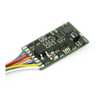
function output A (white cable) to the bulb which is at the front in relation to the direction of
travel
function output B (yellow cable) to the bulb which is at the back in relation to the direction of
travel
If the functions inside the locomotive (e.g. the bulbs of the direction-dependent lights) are not
electrically connected to the chassis (i.e. if they are "potential-free"), connect the other pole of the
function to the blue cable as shown in the illustration (Abb. 1). If a connection between functions
and chassis does exist, the blue cable remains unused. When connected to the blue cable, the
bulbs shine somewhat brighter and, in addition, the direction-dependent lighting then also works in
normal DC operation. Which option you choose depends on the design of the locomotive.
For the connection of the LEDs, note that the blue cable is the positive pole (anode side of the LED)
and the function output is the negative pole (cathode side of the LED). The voltage at the function
output is approx. 16 V. Please do not forget the necessary protective resistor.
Now connect outputs C and D (if your locomotive has further functions):
function output C (green cable) to another locomotive function,
function output D (solder pad) to another locomotive function,.
 Loading...